
Related Manuals for Critical Environment Technologies LPT-M


Summary of Contents for Critical Environment Technologies LPT-M
- Page 1 Operation Manual Rev. B | 2020.11 LPT-M Modbus® Digital Transmitter www.critical-environment.com...
-
Page 2: Table Of Contents
LPT-M - Operation Manual Rev. B | 2020.11 TABLE OF CONTENTS 1 POLICIES ......................6 1.1 Important Note ....................6 1.2 Warranty Policy ....................7 1.3 Service Policy ....................7 1.4 Copyrights ......................8 1.5 Disclaimer ......................9 1.6 Revisions ......................9 2 INTRODUCTION ...................10 2.1 General Description ..................10 2.2 Key Features ....................11... - Page 3 Rev. B | 2020.11 LPT-M - Operation Manual 5.5.1 Wet Environment Considerations ..............5.5.2 EMI and RF Interference Considerations ............5.5.3 Mounting Height (Sensor Dependent) ............5.6 Enclosure Mounting Components ..............27 5.6.1 Enclosure Base ....................5.6.2 Enclosure Bottom .................... 5.7 Wiring Connections ..................28 5.7.1 Power &...
- Page 4 LPT-M - Operation Manual Rev. B | 2020.11 6.9.2 Setting Relay ON / OFF Delay ................6.9.3 Relay Mode of Operation (Normal or FAILSAFE)..........6.9.4 Relay Alarm Level Assignment ................ 6.10 Test Functions ....................47 6.10.1 Test Audible / Buzzer ..................
- Page 5 7.3.5 Fault Reading ....................7.3.6 Calibration Failure ................... 7.4 Calibrating an ESH-A Remote Sensor Connected to an LPT-M ......61 7.4.1 Zero and Span Calibration of a Responsive ESH-A Remote Sensor ....7.4.2 Zero Calibration of a New or Replacement ESH-A Remote Sensor ....
-
Page 6: Policies
LPT-M - Operation Manual Rev. B | 2020.11 1 POLICIES 1.1 Important Note Read and understand this manual prior to using this instrument. Carefully read the warranty policy, service policy, notices, disclaimers and revisions on the following pages. This product must be installed by a quali ed electrician or factory trained technician and according to instructions indicated in this manual. -
Page 7: Warranty Policy
The product is only to be used for the purposes stated in the manual. Critical Environment Technologies is not liable for auxiliary interfaced equipment or consequential damage. -
Page 8: Copyrights
LPT-M - Operation Manual Rev. B | 2020.11 Prior to shipping equipment to CETCI, contact our o ce for an RMA #. All returned goods must be accompanied with an RMA number. If CETCI is to do the repair work, you may send the instrument, prepaid, to: Attention: Service Department Critical Environment Technologies Canada Inc. -
Page 9: Disclaimer
Rev. B | 2020.11 LPT-M - Operation Manual 1.5 Disclaimer Under no circumstances will CETCI be liable for any claims, losses or damages resulting from or arising out of the repair or modi cation of this equipment by a party other than CETCI service... -
Page 10: Introduction
Occupational Health & Safety (OHS) hazardous levels for toxic gases. Operating as a digital transmitter or as a standalone xed system, the LPT-M o ers an audible internal alarm, one dry contact relay, graphic LCD display with user selectable functions, temperature compensation and an automatic thermal resetting fuse all in a RoHS compliant package and standard water / dust tight enclosure. -
Page 11: Key Features
Rev. B | 2020.11 LPT-M - Operation Manual If after reading through the manual, you have any questions, please do not hesitate to contact our Technical Service Department for technical support. 2.2 Key Features • Up to 3 sensor con gurations: single or dual internal electrochemical sensor and/or one remote catalytic combustible or PID TVOC sensor •... -
Page 12: Instrument Specifications
LPT-M - Operation Manual Rev. B | 2020.11 3 INSTRUMENT SPECIFICATIONS 3.1 Technical Speci cations MECHANICAL ABS / Polycarbonate, IP54 rating with splash guard installed. Enclosure Copper coated interior to reduce RF interference. Weight 400 g / 14 oz 127 mm x 127 mm x 71 mm Size 5.0 in x 5.0 in x 2.8 in... - Page 13 Rev. B | 2020.11 LPT-M - Operation Manual Use a magnetic wand to access menu options and initiate Magnetic Sensors calibration without opening the enclosure. Audible Alarm Standard internal buzzer, rated 90 dB @ 10 cm, enable/disable INPUT/OUTPUT Modbus® ID: 100 (default, con gurable)
- Page 14 LPT-M - Operation Manual Rev. B | 2020.11 CERTIFICATION Model: LPT-M-XXX S/N: LPTM1603B00001 Rating: 16-30 VDC, 3W, Class 2 12-27 VAC, 50-60 Hz, 3VA, Class 2 CERTIFIED FOR ELECTRIC SHOCK & ELECTRICAL FIRE HAZARD ONLY. LA CERTIFICATION ACNOR COUVRE UNIQUEMENT LES RISQUES DE CHOC ELECTRIQUE ET D’INCENDIE D’ORIGINE ELECTRIQUE.
-
Page 15: Internal Sensor Gas Types
Rev. B | 2020.11 LPT-M - Operation Manual 3.2 Internal Sensor Gas Types Internal Electrochemical Part Number Range Lifespan Sensors Ammonia (NH LPT-M-NH3 0 - 500 ppm ~2 years Carbon Monoxide (CO) LPT-M-TCO 0 - 200 ppm ~6 years Chlorine (Cl LPT-M-CL2 0 - 5.0 ppm... -
Page 16: Esh-A Remote Sensor Gas Types
LPT-M - Operation Manual Rev. B | 2020.11 Internal Electrochemical Part Number Range Lifespan Sensors continued... Nitrogen Dioxide (NO LPT-M-NO2A 0 - 10 ppm ~3 years Nitrogen Dioxide (NO LPT-M-NO2B 0 - 10 ppm ~6 years Oxygen (O LPT-M-O2 0 - 25% Vol... -
Page 17: Enclosure Dimensions
Rev. B | 2020.11 LPT-M - Operation Manual 3.4 Enclosure Dimensions Above dimensions are shown with optional splash guard. Without splash guard, thickness is 71 mm / 2.8 in. The area required for enclosure door to be open 90 degrees is 178 mm / 7.0 in or 254 mm / 10.0 in for fully open. -
Page 18: Instrument Features
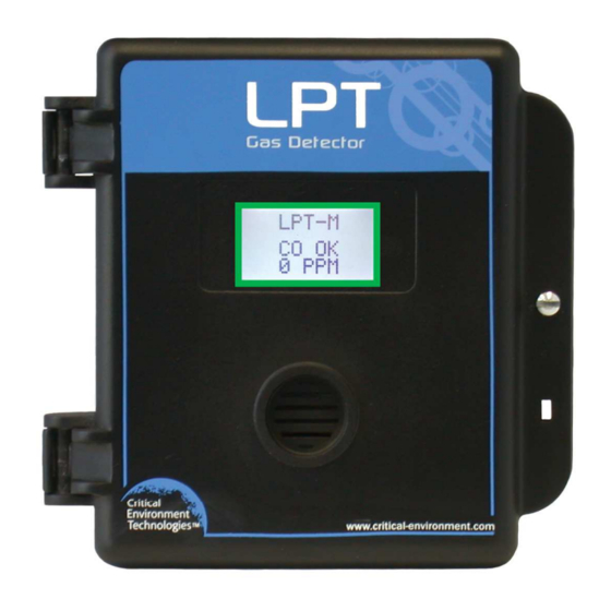
4 INSTRUMENT FEATURES 4.1 Exterior Enclosure Œ • Ž • ‘ • Œ ARROW UP Ž Side view of LPT-M showing ENTER Ž location of Magnetic Sensors. ARROW DOWN Ž © 2020 All rights reserved. Data subject to change without notice. - Page 19 Rev. B | 2020.11 LPT-M - Operation Manual NUMBER FEATURE FUNCTION Secures door to base and allows easy Œ Door Hinge opening and closing Graphic LCD display. Green border • Display with green border indicates transmitter operation is Modbus® Use a magnetic wand to access menu Magnetic Sensors (arrow Ž...
-
Page 20: Interior System Layout
LPT-M - Operation Manual Rev. B | 2020.11 4.2 Interior System Layout Ž Œ • Œ • Œ • ‘ © 2020 All rights reserved. Data subject to change without notice. - Page 21 Rev. B | 2020.11 LPT-M - Operation Manual NUMBER FEATURE FUNCTION Access menu options and program functions using Œ Programming Buttons buttons inside the enclosure. (Arrow up, Enter, Arrow down) • Remote Sensor Terminal Terminal for connecting the ESH-A Remote Sensor Low voltage pluggable terminal for relay connection.
-
Page 22: Installation
5 INSTALLATION The sensor in the LPT-M goes through a burn in period at our factory prior to shipiping so it is ready for operation upon arrival. If you install the LPT-M when it arrives, most sensors will not require a long warm up period (about 5 minutes for Ammonia and Nitrogen dioxide, 2 minutes for the other gases, except Oxygen which is a minimum of 2 hours). -
Page 23: General Safety Warnings
5.2 General Safety Warnings The LPT-M is intended for indoor use, permanently mounted at a height that is appropriate for the type of gas being monitored. See Section5.5 Mounting the Transmitter. The LPT-M should be protected from extreme weather conditions. -
Page 24: Protection Against Mechanical Risks
LPT-M - Operation Manual Rev. B | 2020.11 This device may interfere with pacemakers. Modern pacemakers have built-in features to protect them from most types of interference produced by other electrical devices you might encounter in your daily routine. If you a have a pacemaker, follow your healthcare provider’s instructions about being around this type of equipment. -
Page 25: Mounting The Transmitter
LPT-M - Operation Manual 5.5 Mounting the Transmitter The LPT-M should be installed on a at vertical surface using the four 4.4 mm / 0.175 in diameter mounting holes provided to maintain water tight status. Care should be taken to ensure that the face of the LPT-M is not obstructed in order to maximize the sensor’s exposure to the environment... -
Page 26: Mounting Height (Sensor Dependent)
LPT-M - Operation Manual Rev. B | 2020.11 are still circumstances and levels of interference that may cause our equipment to respond to these interferences and cause them to react as if there has been gas detected. There are some installation procedures that will reduce the likelihood of getting faulty readings: 1. -
Page 27: Enclosure Mounting Components
Rev. B | 2020.11 LPT-M - Operation Manual Chlorine (Cl 15 cm above the oor Commercial swimming pools 6 in above the oor Ozone (O 5.6 Enclosure Mounting Components 5.6.1 Enclosure Base Ž Ž Œ • Œ Ž Ž •... -
Page 28: Enclosure Bottom
• 5.7 Wiring Connections The LPT-M digital transmitter is a low voltage powered device. Any application of operating voltages higher than indicated in the speci cation may result in damage. Double check wiring connections prior to powering the transmitter. Damage from incorrect wiring connections or from too much voltage applied is not covered under warranty. -
Page 29: Power & Output Connections
5.7.1 Power & Output Connections If the LPT-M is being connected to either a QCC or FCS the supply voltage will either be supplied by the QCC or FCS and any additional power requirements of the system will be supplied by RPS-24VDC Remote Power Supply devices. - Page 30 LPT-M - Operation Manual Rev. B | 2020.11 System power: The main wiring terminal strip on the LPT-M circuit board can be unplugged for easier wiring installation. Grasp the two sides of the terminal strip and pull sideways. The wiring should be 4-conductor shielded 16 awg stranded within conduit in a network wiring (daisy-chain) con guration.
-
Page 31: Relay Wiring Connection
Rev. B | 2020.11 LPT-M - Operation Manual Wiring Example: 4-Wire VDC 5.7.2 Relay Wiring Connection The relay operates in “failsafe” mode, i.e. the relay coil is energized under normal non-alarm conditions. The relay is de-energized when if power fails. In most applications the relay function should use the common “COM”... -
Page 32: Esh-A Remote Sensor Wiring Connection
Each ESH-A is given the same serial number as the device it is being connected to. Make sure to connect the ESH-A to the LPT-M that has the same serial number or the system won’t work. Four-conductor, 16 AWG stranded shielded cable is required for the remote sensor wiring. This wiring should be run in a conduit, separate from the signal output, and should not exceed 61 m (200 ft). - Page 33 610 m (2000 ft). It is recommended that an LNK-XT be installed approximately every 32 LPT-M devices, or when a drop in voltage is detected. © 2020 All rights reserved. Data subject to change without notice.
-
Page 34: System Operation & Configuration
(alarms, relays) as it has been con gured. If the BAS / DDC is not requesting information from the LPT-M or it is being used as a standalone device, the LPT-M will operate according to the gas readings, alarm setpoints, buzzer and relay con gurations as outlined in this manual. -
Page 35: Accessing The Menu With Passcodes
Rev. B | 2020.11 LPT-M - Operation Manual ARROW UP - used for going up through the menus or incrementing values or selecting an alpha character ENTER - used pirmarily as an enter key, either for getting to the next screen or... - Page 36 LPT-M - Operation Manual Rev. B | 2020.11 CODE NAME DESCRIPTION • Adjust Display Contrast • Program Audible • Enable / Disable Audible • Audible ON Delay • Audible Alarm setpoints (Low, Med, High, Fault) • Test Audible / Buzzer Hardware •...
-
Page 37: Power Up And Warm-Up
NOTE: The LPT-M will be visible on the BAS / DDC system during the warm-up countdown but a correct reading will not show up until the unit has nished the warm-up period and the sensor(s) has stabilized. - Page 38 LPT-M - Operation Manual Rev. B | 2020.11 If the LPT-M is part of a system, such connected to a QCC or FCS, each gas channel splash screen will show the current status of the channel: • OK - gas channel is operating normally •...
-
Page 39: Set Lcd Display Contrast Level
00 and 35. The factory default contrast level is 20. 6.6 Fault Detection The LPT-M has built in fault detection, and in the event of a problem with the measurement circuitry the transmitter will indicate a fault condition on the display. Normal operation will resume once the fault condition has been corrected. -
Page 40: Modbus® Settings
Individual transmitters being added to an existing system may require changes to the default Modbus® settings. 6.7.1 Change Modbus® ID If required, you can change the Modbus® ID assigned to an LPT-M transmitter. In the Hardware Con guration Menu (passcode 1001), press either ARROW to scroll through the menu and select Modbus®. -
Page 41: Modbus® Holding Registers
6.8 Alarm / Buzzer Operation The LPT-M has an internal buzzer (alarm) that can be enabled or disabled, assigned to a channel alarm level setpoint and con gured to have an ON Delay. The buzzer is linked to the backlight of the display, so that in an alarm condition, the backlight of the display will ash on and o . -
Page 42: Enable / Disable Audible
6.8.2 Audible ON Delay You can set the buzzer to be delayed in sounding for a speci ed period of time after the LPT-M has gone into an alarm state. If the alarm state is neutralized before the time delay expires, the device returns to normal operation. -
Page 43: Audible Alarm Level Assignment
Rev. B | 2020.11 LPT-M - Operation Manual Press ENTER and use the ARROW keys to increase or decrease the number of seconds. Move to the next digit by pressing ENTER. When nished, press ENTER to save and Exit. NOTE: The maximum length of time you can set the audible delay on for is 9999 seconds (2.7 hours). -
Page 44: Relay Operation
6.9 Relay Operation The LPT-M has one dry contact relay that are designed to operate fans or to control equipment that draws no more than 3 volts, 2 amps max at start-up and / or operational current. The system does not provide any power from these terminals. -
Page 45: Setting Relay On / Off Delay
6.9.2 Setting Relay ON / OFF Delay The LPT-M comes with a con gurable ON and OFF delay for its relays. In the event of a gas build up in excess of the level set for the speci ed alarm level, the relay will be triggered. If an ON DELAY has been set, the relay will remain unchanged until the time delay has expired, at which time the relay will “trip”. -
Page 46: Relay Mode Of Operation (Normal Or Failsafe)
6.9.3 Relay Mode of Operation (Normal or FAILSAFE) The LPT-M is designed to be fail-safe so the relay is normally energized in a non-alarm state for failsafe operation. If required, the LPT-M can be con gured for normal relay operation. -
Page 47: Test Functions
Rev. B | 2020.11 LPT-M - Operation Manual NOTE: The LOW, MID and HIGH setpoints of the alarm levels are con gured in the Sensor Con guration Menu. Refer to Section 6.11 Setting Channel Alarm Setpoints. In the Hardware Con guration Menu (passcode 1001), press either ARROW to scroll through the menu and select Program Relay. -
Page 48: Test Relay
LPT-M - Operation Manual Rev. B | 2020.11 Move to the next digit by pressing ENTER. When nished, press ENTER to save and Exit. The test will start immediately and will continue for as long as the time was set. The remaining time of the test can be seen counting down on the display. -
Page 49: Test Gas Reading Response / Send Test Reading To Controller
This test allows you to send a forced gas reading to the controller without having to expose the sensor to actual gas, so you can make sure the LPT-M is connected to the controller properly after installation and is still initiating an appropriate response from the controller during routine maintenance checks. -
Page 50: Setting Channel Alarm Setpoints
Repeat for each channel you want to test. 6.11 Setting Channel Alarm Setpoints The LPT-M is con gurable as a one, two or three channel gas detector and each channel has three gas alarm setpoints, LOW, MID and HIGH which can be ascending or descending. The number entered as the setpoint is the exact number at which the alarm will be triggered, unless a hysteresis value has been set (refer to Section 6.11.4 Setting Hysteresis). -
Page 51: Setting The Mid Alarm Setpoint
Rev. B | 2020.11 LPT-M - Operation Manual Press ENTER and use the ARROW keys to scroll through the menu and choose SP Low. Press ENTER and use the ARROW key to choose ASCENDING or DESCENDING. Press ENTER again to change the setpoint value by using the ARROW keys to increase or decrease the number. -
Page 52: Setting The High Alarm Setpoint
LPT-M - Operation Manual Rev. B | 2020.11 6.11.3 HIGH Alarm Setpoint Follow the same procedure as the 6.11.1 Setting the LOW Alarm Setpoint, choosing the SP High menu option. Default setpoints are as follows: SENSOR GAS TYPE LOW ALARM... -
Page 53: Enable / Disable Channels
) can be substituted for zero air when null adjusting electrochemical sensors. Contact CETCI for clari cation. Every LPT-M transmitter is calibrated in a chamber by true di usion method prior to leaving our facility. This method more closely emulates actual “real world” conditions. Field calibration... -
Page 54: Regulators & Flow
The proper calibration adapter should be utilized to allow the gas to properly di use around the sensor. The calibration adapter plug for an LPT-M with an internal sensor without a splash guard is part number CET-7000-CAP. For an LPT-M with a splash guard, use part number CET-4700-SCC or use the Cal Clip hands free adapter, part number CET-SGC. -
Page 55: Gas Testing Frequency (Bump Testing)
If a splash guard is required for an LPT-M Modbus® Transmitter with an Ozone, Chlorine, Chlorine Dioxide, Hydrogen Chloride, Hydrogen Cyanide or Phosphine sensor the special sticky gas splash guard (Option -SN) must be ordered. -
Page 56: Calibrating The Internal Sensor(S)
LPT-M - Operation Manual Rev. B | 2020.11 (see Section 8.4 Calibration Kit and can also be ordered separately from CETCI under part number CET-MW. To initiate non-intrusive calibration, touch the magnet to one of the marks on the side of the enclosure and follow the screen prompts along with the instructions in this section. - Page 57 Rev. B | 2020.11 LPT-M - Operation Manual When the process has nished and the Zero calibration was accepted, press ENTER to Exit and remove the cylinder of zero gas. Refer to Section 7.3.3 Zero - Requires Override if the Zero calibration was not successful.
-
Page 58: Troubleshooting Calibration
LPT-M - Operation Manual Rev. B | 2020.11 When the correct value is displayed, attach the regulator to the span gas cylinder and ow the span gas over the sensor. Once gas is detected, display will show a countdown from 180 seconds (3 minutes). -
Page 59: Calibration Adapter Plug
If all that is desired is to do a zero calibration shift, complete Step 1 in Section 7.2 Calibrating the Internal Sensor(s). A zero shift calibration is only done when the LPT-M is being installed for the rst time. The reason for a zero shift calibration is to compensate for the new environment in which the LPT-M is being installed. -
Page 60: Fault Reading
In either case all that can be done is to attempt a complete calibration from the beginning (Step 1) and determine if this corrects the fault. If a calibration does not resolve the fault then the LPT-M may need a new sensor. If that does not correct the fault, please contact our Technical Service Department at help@cetci.com. -
Page 61: Calibrating An Esh-A Remote Sensor Connected To An Lpt-M
If the sensor does not need to be replaced and is responding correctly, the Zero and Span calibrations will need to be done at LPT-M transmitter that the ESH-A is connected to. In the Sensor Con guration Menu (passcode 3032), press either ARROW key to scroll through the menu and select the channel the ESH-A is assigned to. -
Page 62: Calibrating An Oxygen Sensor
ESH-A board), adjust the voltage to read 0.40 VDC. Verify that the voltage output from digital multi-meter leads attached to test points TP1 and TP2 on the LPT-M is reading 0.0 VDC (a Zero and Span Calibration of the LPT-M will be required if this is not the case). - Page 63 Rev. B | 2020.11 LPT-M - Operation Manual The factory default calibration gas concentration is: SENSOR GAS TYPE CALIBRATION GAS LEVEL Oxygen (O 20.9% VOL Either use a cylinder of 20.9% Oxygen or if you are con dent of the air quality, the oxygen in the breathing environment can be used as a fairly accurate source of span gas (be careful not to exhale in the direction of the Oxygen sensor vent).
-
Page 64: Accessories
LPT-M - Operation Manual Rev. B | 2020.11 Step 2 In the Sensor Con guration Menu (passcode 3032), press either ARROW key to scroll through the menu and select the channel with the Oxygen sensor you want to calibrate. Press ENTER and use the ARROW key to scroll to Calibrate Zero. -
Page 65: Calibration Adapter Clip "Cal Clip
8.2 Calibration Adapter Clip “Cal Clip” (p/n: CET-SGC) To calibrate an LPT-M with a factory installed splash guard (Option -S), attach the Cal Clip around the splash guard. The small barb hose tting accommodates standard or Te on tubing of 1/8”... -
Page 66: Calibration Kit
LPT-M - Operation Manual Rev. B | 2020.11 to the sensor. With only four slotted mounting holes, installation and removal for gas detector servicing is easy. In applications where sticky gases are being monitored, such as Ozone, Chlorine Hydrogen Chloride, etc. and frequent wash-downs are required, the metal guard can be ordered with a splash cover (p/n: SCS-8000-WSG). -
Page 67: Maintenance
Canada to other countries, including the USA. 9 MAINTENANCE The LPT-M transmitter requires virtually no maintenance other than regular calibration of the sensor(s). There are no replaceable components except the sensors. The transmitter should be monitored for possible damaging conditions. -
Page 68: Trouble Shooting
Check the display contrast. Refer to Section 6.5 Set LCD Display Contrast Level. Display shows a channel status FAULT message. The LPT-M is in fault mode. If re-calibrating the sensor fails, replace the sensor. Display shows “Calibration Failure”. The span calibration failed. Try to recalibrate the sensor again. If re-calibrating the sensor fails, replace the sensor. - Page 69 Rev. B | 2020.11 LPT-M - Operation Manual this information ready to relay to our technician. In the Sensor Con guration Menu (passcode 3032) press either ARROW key to scroll through the menu and select the gas channel for which you want to see the diagnostic information. Press ENTER and then the UP ARROW key to see this diagnostics screen.
- Page 70 LPT-M - Operation Manual Rev. B | 2020.11 NOTES © 2020 All rights reserved. Data subject to change without notice.
- Page 71 Rev. B | 2020.11 LPT-M - Operation Manual NOTES © 2020 All rights reserved. Data subject to change without notice.
- Page 72 Critical Environment Technologies Canada Inc. Unit 145, 7391 Vantage Way, Delta, BC, V4G 1M3, Canada Toll Free: +1.877.940.8741 Tel: +1.604.940.8741 www.critical-environment.com LPT-M20201116-B © 2020 Critical Environment Technologies Canada Inc. All rights reserved. Data in this publication may change without notice.
Need help?
Do you have a question about the LPT-M and is the answer not in the manual?
Questions and answers