Advertisement
Quick Links
Advertisement

Related Manuals for Caple WI6130WH


Summary of Contents for Caple WI6130WH
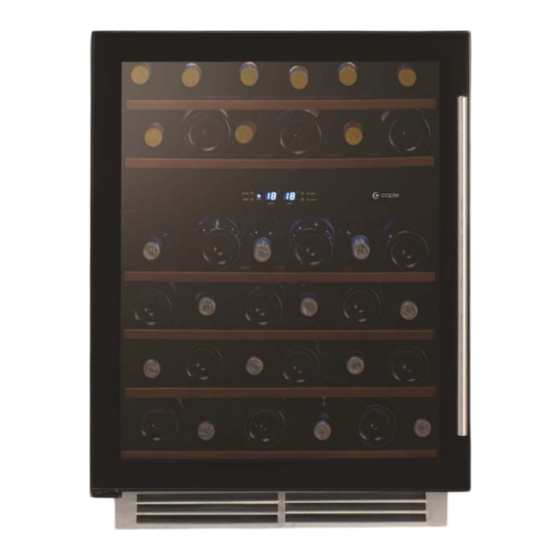
- Page 1 WI6130WH Caple 60cm wine cabinet Technical information Technical information...
- Page 3 WI6130WH - Caple 60cm wine cabinet Item Part Code Description DG13-1 Water box DG2-14 Power cord DG1-93 Compressor DG13-272-1 Electrical box cover DG6-15 Transformer DG3-100-9 PCB board DG26-192 Cabinet DG13-268 Decorative nail DG14-190-SR Top right hinge DG12-1-2 Evaporator DG13-7 Shelf support...
- Page 4 WI6130WH - Caple 60cm wine cabinet Item Part Code Description DG13-129 LED light cover DG3-14-W LED light DG12-91 Condenser DG19-9 Condenser cover DG7-3.2-BH Condenser fan DG17-145-2 Wire DG19-3 Fan cover DG12-6.1 Air-circulating pipe DG22-331 Compressor bracket DG11-45 Dry filter DG13-3149...
- Page 5 WI6130WH Caple dual zone wine cabinet Caple dual zone wine cabinet Service Manual...
- Page 6 Service Manual JG Series Electronic Dual Temperature Zone Wine Cellar。 JG Series Electronic Dual Temperature Zone Wine Cellar is including Model JG32A , JG45B, JG50B , JG50B-1,JG50FB。 The content below shows different default might happen when the wine cooler is working, and also shows how to find the defaults and repair the defaults.
- Page 7 ▲ Noise problems ○Compressor noise .…………………………………………………..……………………………(Page 13) ○ Fan noise …………………………………………………………..………. …………………(Page 13) ……...…………………………………………...………………………… ○ Refrigerant jet noise (Page 15) ……………………...………...……………………. ………………... ○ Capillary vibration noise (Page 15) ○ Oil jam noise ……………………………………..…...…………………. …………………(Page 15) ▲ Evaporator freezing problems ... ………………………………………...……………………..(Page 15) ▲...
- Page 8 △ Cooling system faults. ○ How to diagnose faults: It should take approximate 3 hours to reach the lowest setting temperature of 5℃ for an empty unit (assuming ambient temp of 32 degrees centigrade and continuous operation). If not, check the compressor, cooling fans, controller, and sensors. If all these are working normally, there is probably a cooling system’s fault.
- Page 9 the unit the compressor should automatically stop within - 2.5 deg centigrade of the set temperature and start with +2.5 deg centigrade of the set temperature within approx 3 hours (assuming an ambient temperature of 32℃and the unit is empty). ○...
- Page 10 c. Drive up the shelves make it above the fixer 1 (Fig.3),then take it out according to the arrowhead Fdirection(Fig.3.1) Fig.3 Fig.3.1 d. Pull the shelves to the bottom, circumvolve any side of the right and left, and let the setter of the shelve go out of the channel, and then draw out the shelves.
- Page 11 a.Remove the shelf, and remove the screw(1,2,3,4) of the middle air-duct cover (Fig.5). (Please noted: one the below diagram, the diagram on the right side is to desribe the spare parts on the PCB board. If there is any similar situation, use the same method. ) Fig.5 b.Pull out electric box to expose the control panel as per the direction of arrowhead, then unplug all the connectors from the control panel, and remove electric box (A).
- Page 12 Fig.7 New version control panel connections 1. To the fan of the refrigeration compartment (F3 White). 2. To the air cycling fan.(F2 Yellow) 3. To the fan of the freezing compartment.(F1 red) 4. To the sensor of the freezing compartment (X1 yellow) 5.
- Page 13 d.Take off the screws of middl air-duct (12, 13, 14, 15, 16, 17), remove the upper cover of the middle air duct board(G), and expose the air-duct cover. (Fig.9) Fig.9 ② The new structure electrical removement. a. Remove the shelves then remove the fixing screws (2,3). (The right diagram shows the box for clarity only, ). (Fig 10) Fig.10 b.
- Page 14 c. Remove the fixing screws (7,8,9,10,11,12), then pull out electric box (C) to expose the air duct board; (Fig.12) Fig.12 ③ The divide structure electrical removement.(in this version PCB board is devide into 2 blocks,one is power PCB,the other is control PCB, a.
- Page 15 Fig.15 1. To the display PCB (connect to 11) 2.To the display PCB (connect to 12) 4. To the sensor of the refrigeration compartment (Yellow ) To the sensor of the evaporator (White) 5. To the sensor of the freezing compartmen (Red ) 6.To LED light(Black)...
- Page 16 Fig.17 b.Remove the fixing screws of air duct board (1,2,3,4,5,6), then pull out air duct board (A). See (Fig 18) Fig.18 4>. For a View of the internal configuration after removal of the air duct board, see (Fig.1 ○ Front side joints location. See (Fig.19) A.
- Page 17 ○ Rear side view of the joints position(there are two types condensers inner style and outer (Fig.20) style (Fig.21 & Fig.21.1) B. Dry filter process pipe soldered joint C. Dry filter soldered joint. D. Capillary soldered joint E. Process pipe soldered joint. F. Suction pipe soldered joint G.
- Page 18 ▲ Heating system faults ○ How to diagnose faults: If the temperature of refrigeration compartment is (-2℃) lower than setting temperature for an empty unit (assuming ambient temp of over 0 degrees centigrade and continuous operation and normal temperature of the freezing compartment), check the heater fan and PTC heater.
- Page 19 Fig.22 Fig.22.1 b.How to replace air circulating fan 1). Remove the shelf 2). Regarding the new structure eletrical box, only remove the up cover of middle upper air-duct board , and remove the screw air cycling fan and replace with a new (Fig.10) (1,2,3,4), and remove the (Fig.23)
- Page 20 Fig.25 c. How to replace the the condenser fan(noted: there are different structure and the fan installing position, but almost the same installation methods). Please see as below. 1>. Remove the spring (A), and remove the compressor electrical cover(B)(Fig.26). 2>. Remove the two terminal of the fan electrical code(C, D) , mark them before removement to avoid mistake(noted: the diagram below take ZEL compressor as a sample).
- Page 21 ○ Capillary vibration noise Default: high frequency impact noise in capillary Zone. Caused by either: 1>. The capillary being insert too deep into the evaporator, so when the refrigerant is Jetting, the end of vibrating capillary will hit the inside of the evaporator. 2>.
- Page 22 ▲ Unstable temperatures inside the cabinet. The unstable temperature is caused by the evaporator fans cease, and it can be check by the below method: When the compressor is running, the light “Run” is on, the fan should be running, if the fan stop, check the whether is any (Fig.22) fault in the fan or fan connection.
- Page 23 and the sensor should be replaced see (Page 19). 7>. If the LED displays “E8” indicates a refrigeration compartment sensor short circuit fault and the sensor should be replaced see (Page 19). 8>. If the LED displays 37℃, this default only happen in the old model. Bescause the old machine use the old PCB board.
- Page 24 Fig.29 a. As to the sensor in the point A, remove the air-duct board firstly(Page 4), and remove the fixing screw, then take off the sensor, and then unplug another socket X 1 of the sensor in the PCB control penal board in the (Fig.7), and it can be replace it with the same model.
- Page 25 c. Prepare two heat compressing pipe.(specification: inner diameter φ 2.5mm × 25mm) prepare a sensor, specification as the diagram (C) (D). d.Divide the two heat compressing pipe, and insert them into the wire terminal of the sensor, and connect them spare sensor with the wire, and connect the heat compressing pipe with the middle of the conjunction, dry them until they are tight(E).
- Page 26 Fig.32 ② The new structure electrical removement. a. Remove the the shelf , and remove the upper cover of the air-duct panel, expose the whole PCB board( Fig.8 ) b.Unplug all the connector, press the 4 studs(6) one by one. Updraw the PCB board, and draw off the PCB board(C), , replace it with the same model’s PCB board.
- Page 27 Fig.33 ③ The divide structure electrical removement.(in this version PCB board is devide into 2 blocks,one is power PCB,the other is control PCB) A. How to replace the control PCB a. Remove the the shelf , and remove the upper cover of the air-duct panel( Fig.13), expose the whole board( Fig.34 )
- Page 28 Remove two fixing screw(3) of the transformer, take off the tranformer(B)for replacement. ( Fig.35) (Fig.36) Divide version control panel connections Fig.35 Fig.36 1.Heater connector (White) 2.Outer fan connector (Red) 3.To control PCB(White) 4. Compressor connecter 5.Connectors of the power N 6.
- Page 29 c. Remove the shelves,take the up cover of the middle air duct board, remove the screws(1,2) fixing (Fig. 38) the lamp hold,remove the bulb according to the direction arrowhead show, replace the bulb. Fig. 38 2 >. How to replace the LED light A.How to replace the LED light in upper zone(Fig.39 ) a.Remove the shelves.
- Page 30 ②, Unplug the LED light connector, press the 4 studs one by one,take the LED light upward,replace it. ( Fig.34) ○ How to replace the decorative frame Remove the screw(1,2,3),pull the decorative frame according to the arrowhead that view K show,then remove the screw(4,5,6) from the gap betoween decorative frame and cabinet,remove the decorative frame.
Need help?
Do you have a question about the WI6130WH and is the answer not in the manual?
Questions and answers