Table of Contents
Advertisement
Quick Links
Model #
114W
Chef's Dropleaf
Island
Assembly Instructions
Congratulations!
This fine piece of furniture will make a handsome
addition to your home. For the best results, start by
reading both the Assembly Instructions and
Finishing Hints before you begin your project.
For normal household use only.
recommended for commercial use.
Do not climb, sit or stand on this piece of
furniture.
P.O. Box 2827
Eugene, OR 97402 USA
Service Policy:
which are defective, missing or damaged
during assembly. Please contact Whittier
Wood Products customer service department
directly (by phone, fax, mail or email) for
replacement parts.
Hours:
Our friendly customer service staff
can be reached Monday-Friday 7:00 a.m. to
5:00 p.m. (Pacific Time). A message can be
left 24 hours a day, 7 days a week.
To Order:
Provide the complete furniture
model number (upper left corner of this
page), part letter, production code, quantity
needed, reason for replacement and your full
name and address along with a telephone
number in case we need to contact you.
Parts ship from our Eugene, Oregon factory
within 1 or 2 business days from the time
we receive the request. Please allow 5-10
business days for delivery.
Outside U.S. or Canada: 541-687-0213
Outside U.S. or Canada: 541-687-0213
Fax: 541-687-2060 • Email: info@whittierwood.com
Fax: 541-687-2060 • Email: info@whittierwood.com
Mail: P.O. Box 2827 • Eugene, Oregon 97402, U.S.A.
Mail: P.O. Box 2827 • Eugene, Oregon 97402, U.S.A.
Read both the Assembly Instructions and Finishing
Hints completely before beginning.
If you choose to use the top for food preparation, it
should be finished with a non-toxic substance such
as mineral oil or butcher block oil.
Store the parts: 1) in their box; 2) in a dry place; 3) in
temperatures ranging from 40° to 90°. (Not on a cold,
possibly damp, cement floor.)
Inspect your furniture periodically for any loose glue
joints or screws, or any other problem which may
be affecting the stability of your furniture. Tighten or
repair as needed.
Production Code:
We will replace any parts
Rev. 10/05
Advertisement
Table of Contents

Related Manuals for Whittier Wood Products Chef's Dropleaf Island 114W


Summary of Contents for Whittier Wood Products Chef's Dropleaf Island 114W
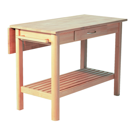
- Page 1 Model # 114W Chef’s Dropleaf Service Policy: We will replace any parts Island which are defective, missing or damaged during assembly. Please contact Whittier Assembly Instructions Wood Products customer service department directly (by phone, fax, mail or email) for replacement parts. Hours: Our friendly customer service staff can be reached Monday-Friday 7:00 a.m.
-
Page 2: Top Assembly
114W Chef’s Dropleaf Island — Parts List BEFORE BEGINNING ASSEMBLY, check that the quantities of the parts received match those on the parts list below. TOP ASSEMBLY A – Top – Qty. 1 B – Leaf – Qty. 1 C – Front Apron – Qty. 1 (not shown) (attached) N –... -
Page 3: Special Instructions
114W Chef’s Dropleaf Island — Parts List (cont.) O – Rack Brace – Qty. 3 P – Leaf Support – Qty. 2 S – #7 x 1½" Type 17 Pan R – Wooden Dowel – Qty. 12 Head Screw – Qty. 28 Q –... -
Page 4: Tools Required
114W Chef’s Dropleaf Island ASSEMBLY INSTRUCTIONS TOOLS REQUIRED: Phillips Head Screwdriver, Adjustable or 9/16" Wrench, and Wood Glue. IMPORTANT NOTE: We recommend finishing the unit before final assembly. Before finishing, read enclosed finishing hints. GROOVE FIG. 1 ASSEMBLE THE RACK: 1) Lay the six Slats (L) face down and attach a Rack Brace (O) at each end of the slats with #7 x 1½"... - Page 5 FIG. 3 FIG. 3A ATTACH RACK SUPPORT TO RACK: 3) On a flat surface, lay the Rack Support Assembly over the Slat Assembly. Attach the Rack Braces (O) to the Rack End Supports (K) with two #7 x 1½" Type 17 Pan Head Screws (S) through the two holes in the inner edge of the end supports.
- Page 6 FIG. 5 ASSEMBLE AND INSTALL TOWEL BAR: 5) Glue the chucked end of the Towel Bar Supports (G) into the holes in the Towel Bar (F). Decide which end of the island you would like to have the towel bar. To attach the Towel Bar Supports (G) to the End Apron (E), start two #10 x 2"...
- Page 7 " FIG. 7 FIG. 7A LEAF 7) Using the enclosed template, mark the locations of the screw holes for the Leaf Supports (P) on the apron 3 " from the top and approximately 3" from the leg. See FIGURES 7 and 7A. Using a Phillips Head Screwdriver, punch a pilot hole for each screw.
- Page 8 Page 8 — 114W...
- Page 9 Modelo # 114W Mesa Central de Cocina con Hoja Abatible Normas para obtener servicio: Reemplaza- remos las piezas que tengan defectos, falten o se Instrucciones para Armar dañen durante el armado. Sírvase comunicarse con el departamento de servicio al cliente de Whittier Wood Products directamente (por teléfono, fax, correo o e-mail) para obtener piezas de repuesto.
-
Page 10: Herramientas Necesarias
Mesa Central de Cocina con Hoja Abatible – Lista de piezas ANTES DE COMENZAR A ARMAR EL MUEBLE, verifi que que haya recibido todas las piezas que se indican en la lista de piezas a continuación. Cantidad Cantidad ENSAMBLE DE LA PARTE SUPERIOR Tablillas de la rejilla . - Page 11 114W — INSTRUCCIONES PARA ARMAR troncocónica #7 x 1½" tipo 17 (S) a través de los dos FIG. 7 – LONG ARM = BRAZO LARGO; orifi cios de los soportes laterales. Asegúrese que los APRON = FALDÓN extremos de las tablillas estén a la misma altura en TOP = PARTE SUPERIOR;...
- Page 12 No. de modèle 114W Îlot de préparation Politique de service : Nous remplacerons toutes les pièces défectueuses, manquantes ou endom- culinaire à abattant magées pendant le montage. Veuillez contacter directement le service clientèle de Whittier Wood Instructions de Montage Products (par téléphone, fax, courrier ou e-mail) pour obtenir les pièces de remplacement.
-
Page 13: Outils Nécessaires
Nomenclature des pièces AVANT DE COMMENCER LE MONTAGE, assurez-vous que les quantités de pièces reçues correspondent à la nomenclature des pièces fi gurant ci-dessous. Quantité Quantité MONTAGE DU DESSUS L Traverse ....... .6 A Dessus . - Page 14 114W – INSTRUCTIONS DE MONTAGE dans le trou situé sur le bord intérieur des supports FIXATION DE L’ABATTANT : d’extrémité de la claie et assujettissez les supports 6) Le dessus étant posé face sur le dessous sur une avant/arrière de la claie. Voir la FIGURE 2. surface protégée, placez l’abattant (B) contre le bord arrière du dessus.
Need help?
Do you have a question about the Chef's Dropleaf Island 114W and is the answer not in the manual?
Questions and answers