
Subscribe to Our Youtube Channel
Related Manuals for THK PCT


Summary of Contents for THK PCT
- Page 1 тел. +7(499) 703-39-86 www.thk.ru sales@thk.ru THK Electrical Actuator Press Series PCT/PC INSTRUCTION MANUAL No.369M Ver 3.00E...
-
Page 2: Table Of Contents
6-4 Periodical inspection ______________________________________________ 6-2 6-5 Lubrication ______________________________________________________ 6-3 6-6 Method for supplying grease (PC) __________________________________ 6-4 6-7 Method for supplying grease (PCT) _________________________________ 6-6 7. Appendix 7-1 Motor mounting procedure (PCT) ___________________________________ 7-1 7-2 Replacement of timing belt procedure (PC) __________________________ 7-7... -
Page 3: Introduction
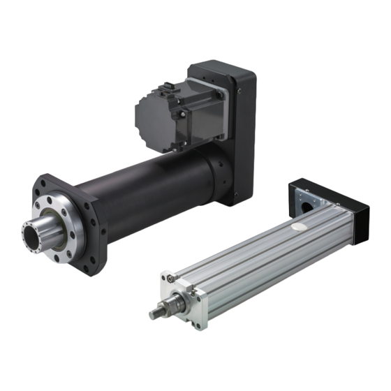
„ This product (PCT) is a cylinder type electrical actuator using ball screws. „ This manual describes the structure of the press series PCT/PC (main unit), and the correct method for handling, installing and maintaining the product. -
Page 4: Safety Precautions
If two or more people are involved in the installation or maintenance work, confirm the procedure, signs and actions to cope with anomalies or the like in advance, and separately appoint a person for monitoring the work. Failure to do so may cause an unexpected accident. PCT/PC... - Page 5 Doing so may cause fault due to entering of foreign material or adversely affect the performance or service life. Or may cause abnormal operation that could lead to injury. * If you wish to disassemble or alter the product, contact THK. PCT/PC...
- Page 6 Failure to do so may cause the product to fall, leading to injury, or cause fault or fracture of the product. * For the weight of the product, see the catalog of press series PCT/PC. „ Installation and operation z Firmly secure this product before operating it.
-
Page 7: Structure And Mode
(each cable is 5 m) come with the product. For the cable model (manufacturer), see the catalog of press series PCT/PC. For the details of cables, contact the manufacturers. * When you use PC30 or PC40 in combination with Servo driver controller THC, you can select the cable length between motor and THC from 3 m, 5 m and 10 m. - Page 8 Steady rest Cover Head bolt Angular bearing Stopper Motor Coupling Lock nut Fig. 1-2-a Press series PCT structure and part names (direct motor coupling) Motor bracket Pulley A Motor Pulley B Pulley plate Pulley cover Belt Fig. 1-2-b Press series PCT structure and part names (motor return) * When you use the product in combination with Servo driver controller TLC or THC, you can select the cable length between the motor and TLC/THC from 3 m, 5 m and 10 m.
-
Page 9: Model Configuration
3. Structure and Mode Model configuration „ PCT/PC model configuration (Combination of Servo Driver Controller TLC/THC) The following is an example of model configuration. PC30 - 06A - 0200 A - R - TH - R / M40B D00 D2 F3 ①... -
Page 10: Storage And Transportation
Failure to do so may cause the product to fall, leading to injury, or cause fault or fracture of the product. * For the weight of the product, see the catalog of press series PCT/PC. PCT/PC... -
Page 11: Precautions To Be Observed For Prevention Of Fault, Fracture, Or Low Performance Of This Product
• Place where a vibration or shock does not transmit to the main unit z When storing this product, enclose it in a package designated by THK and store it in a horizontal orientation while avoiding high temperature, low temperature and high humidity. -
Page 12: Installation And Operation
Doing so may cause injury or machine failure. z Do not use the product with applying radial load and moment load to the rod part. Doing so may cause fault or damage. Or may cause abnormal operation that could lead to injury. PCT/PC... -
Page 13: Precautions To Be Observed For Prevention Of Fault, Fracture, Or Low Performance Of This Product
After trial run, supply the specified grease to ball spline (only PC) and ball screw before using the product. PC Design Symbol A (standard model) contains THK L500 grease. PCT (standard product) contains THK AFB-LF grease. z While PC is provided with a rod retainer inside the product, provide a separate stopper outside of the device to prevent the rod from colliding with the retainer. -
Page 14: Other Precautions
Table 1-1 Models of Standard Timing Belts Design Symbol A (Gates Unitta Asia Company) Model number Motor capacity Timing belt model PCT20R 50 W 196-2GT-6 100 W 273-3GT-6 PCT25R 200 W 273-3GT-9 Table 1-2 Models of Standard Timing Belts (Gates Unitta Asia Company) PCT/PC... -
Page 15: Mounting Method (Pc)
④ Adjust the position so that the center of the mounting hole of PC’s flange and that of the screw hole of the mounting surface match. ⑤ Using the recommended bolt listed on Table 2, apply temporary fastening. ⑥ Using a torque wrench, fasten the bolts. The material of flange is SS400. PCT/PC... -
Page 16: Mounting Method (Pct)
5. Installation and Operation Operation Mounting method (PCT) Fix this product using hexagonal-socket-head type bolt (tensile strength rank 10.9 or higher) through the holes for securing flange or through T slots on the side surface of the unit base with square nuts (attached to the product). - Page 17 If there is any burr or scratch, remove it with an oilstone or the like. Also, remove dust with a clean waste cloth or the like. ② Likewise, confirm that there is no burr, dent or dust on the mounting surface of PCT, and remove it as necessary.
-
Page 18: Maintenance
Doing so may ignite the grease, which could cause fire. * For other information on handling grease, see the precautions indicated on the grease package or catalog. We have “Safety Data Sheets” for THK original greases. Contact THK for details. Precautions to be observed for prevention of fault, fracture, or low performance of this product z To have this product fully exerts its functions, it is essential to lubricate the product. -
Page 19: Daily Inspection
• Inspect whether the mounting bolts are loosened, and retighten it as necessary. • Check the timing belt state (wear, scratch, crack, noise, etc.). When any anomaly (abnormal wear, scratch, crack, etc.) is found, replace the timing belt. * See the appendix “Replacement of timing belt procedure.” PCT/PC... -
Page 20: Lubrication
After trial run, supply the specified grease to ball spline (only for PC) and ball screw before using the product. PC Design Symbol A (standard model) contains THK L500 grease. PCT (standard product) contains THK AFB-LF. z For the greasing interval, if normal operation that pressure is applied at one end of stroke, replenish grease approximately every 500 km travel distance or 6 months, whichever is earlier. -
Page 21: Method For Supplying Grease (Pc)
Supply grease from the grease nipple attached to the housing using the grease gun. „ Ball spline lubrication 1. Wipe off the old grease adhering to the rod. 2. Supply grease from the grease nipple attached to the external cylinder using the grease gun. PCT/PC... - Page 22 5. Move the rod over the entire stroke to apply the grease. * Apply a small amount of grease several times. A-MT6 × 1 type Fig. 3-2 Shapes of the grease nipples z The appendix introduces the grease gun unit for lubrication for your reference. PCT/PC...
-
Page 23: Method For Supplying Grease (Pct)
тел. +7(499) 703-39-86 www.thk.ru sales@thk.ru 6. Maintenance 6. Maintenance Method for supplying grease (PCT) The following shows a representative greasing method: Ball screw grease hole Plug Ball screw greasing position dimension H Fig3-3 Greasing parts „ Ball screw lubrication 1. Move the rod to ball screw greasing position. -
Page 24: Appendix
тел. +7(499) 703-39-86 www.thk.ru sales@thk.ru 7. Appendix 7. Appendix Motor mounting procedure (PCT) The following shows how to mount the motor for your reference: Work procedure and precautions Remove the pulley cover. 1. Loosen the cross recessed button-head bolt. 2. Remove the pulley cover. - Page 25 Use M4 x 4L for hexagonal socket-head setscrews, with steel (45H) cup point. Tightening torque should be 133N·cm. c) For method S of fixing motor shaft Fasten the clamp pulley hexagonal-socket- head type bolt. (See Table 5) Adjust with the straight shaft. Clamp pulley PCT/PC...
- Page 26 Pay attention to which way the motor connector faces. Make sure that the bolts used are not so long as to protrude from the motor bracket end. Motor capacity Motor bracket thickness The number of Tightening torque Model [mm] bolts [N·cm] PCT20R PCT25R PCT/PC...
- Page 27 1. Mount the motor bracket. 2. Temporarily fasten the hexagonal socket- head bolt on the long hole part. Motor bracket Confirm the pulley position 1. Place a straight-edge etc. along the A surface to confirm that the surface matches. A Surface PCT/PC...
- Page 28 (See Table 7 and Table 8) 5. After rotating the pulley and fitting the belt, check that the belt tension is within the specified value. If not within the specified value, loosen the hexagonal socket-head bolt to adjust the tension. PCT/PC...
- Page 29 1. Run for a few minutes and check the following items: · The belt does not get on the flange. · The belt is not resonating. · There is no jumping in the belt. · The tension does not decrease abnormally. PCT/PC...
-
Page 30: Replacement Of Timing Belt Procedure (Pc)
Loosen the tension and remove the belt. 1. Loosen the bolt on the long hole part. 2. Loosen the hexagonal nut and loosen the set screw for adjusting the tension. 3. Bring the motor close to the main unit side. 4. Remove the belt. PCT/PC... - Page 31 4. After rotating the pulley and fitting the belt, check that the belt tension is within the specified value. If not within the specified value, loosen the setscrew for adjusting the tension and hexagonal socket-head bolt to adjust the tension (procedure 2, 3.) PCT/PC...
- Page 32 PC30-06A 340-EV5GT-9 PC40-06B 400-EV5GT-9 PC40H-08C 560-EV8YU-15 16.2 PC50-06D 560-EV8YU-15 16.2 PC60-10E 704-EV8YU-20 21.5 PC60H-10F 720-EV8YU-25 26.9 PC80L-12G 984-EV8YU-40 3.33 46.2 PC80-12G 984-EV8YU-40 3.33 46.2 PC80H-12G 984-EV8YU-40 3.33 46.2 Table 10 Parameters to use the push gauge (Design Symbol A) PCT/PC...
- Page 33 1. Run for a few minutes and check the following items: · The belt does not get on the flange. · The belt is not resonating. · There is no jumping in the belt. · The tension does not decrease abnormally. 7-10 PCT/PC...
-
Page 34: Replacement Of Timing Belt Procedure (Pct)
тел. +7(499) 703-39-86 www.thk.ru sales@thk.ru 7. Appendix 7. Appendix Replacement of timing belt procedure (PCT) The following shows how to replace the timing belt for your reference: Work procedure and precautions Remove the pulley cover. 1. Loosen the button-head bolt. - Page 35 5. After rotating the pulley and fitting the belt, check that the belt tension is within the specified value. If not within the specified value, loosen the hexagonal socket-head bolt to adjust the tension (procedure 2, 3 and 4.) 7-12 PCT/PC...
- Page 36 1. Run for a few minutes and check the following items: · The belt does not get on the flange. · The belt is not resonating. · There is no jumping in the belt. · The tension does not decrease abnormally. 7-13 PCT/PC...
-
Page 37: Replacement Of Motor Procedure (Pct)
тел. +7(499) 703-39-86 www.thk.ru sales@thk.ru 7. Appendix 7. Appendix Replacement of motor procedure (PCT) The following shows how to replace the motor for your reference: Work procedure and precautions Remove the cover. 1. Remove the thin head screws. 2. Remove the cover. - Page 38 100 to 110 SFC-020DA2-8B-8B M2.5 100 to 110 PCT25 SFC-025DA2-8B-14B M2.5 100 to 110 Table 16 Tightening torque of fastening bolt on coupling Mount the pulley cover. 1. Mount the cover. 2. Fix the cover with button-head bolt. 7-15 PCT/PC...
-
Page 39: Permissible Input Torque
Pulling [kN] 10.9 17.8 direction *Load capacity when the actuator is static. *If moment load is applied to the rod, contact THK. „ PCT PCT20 PCT25 Model number Permissible axial load 3240 5850 *For the PC motor mounting and replacement procedures, contact THK. -
Page 40: Introduction Of The Grease
Accepted Startup Low temperature torque: mN·m (-20°C) Rotation 4-ball test (fusion load): N 3089 ASTM D2596 Operating temperature range: °C -15 to 100 Appearance color Brownish yellow Fig. 4 Appearance of the grease tube and the product box 7-17 PCT/PC... - Page 41 Oil separation rate: mass% (100°C, 24 h) JIS K2220.11 Low temperature torque: mN·m (-20°C) 110/50 (start/rotation) JIS K2220.18 Operating temperature range: °C -20 to +175°C Appearance color Yellow Fig. 5 Appearance of the grease tube and the product box 7-18 PCT/PC...
-
Page 42: Introduction Of The Grease Gun Unit
Table 19 shows the specifications of the grease gun while Fig. 6 shows its appearance. Discharge pressure 19.6 MPa max Discharge rate 0.6 cc/stroke Grease 70 g bellows cartridge Overall length 235 mm (excluding nozzle) Mass 480 g (with nozzle, excluding grease) Table 19 Specifications of the grease gun 7-19 PCT/PC... - Page 43 7. Appendix Fig. 6 Appearance of the grease gun Fig. 7 shows the shapes of the nozzles and attachment for the grease gun used to lubricate this product. H Type Fig. 7 Shapes of nozzles for the grease gun 7-20 PCT/PC...
- Page 44 тел. +7(499) 703-39-86 www.thk.ru sales@thk.ru Appendix Revision history Th e in s t r u ct i o n ma n ua l N o. i s d es c r ib e d o n t h e b ack cov er.
- Page 45 тел. +7(499) 703-39-86 www.thk.ru sales@thk.ru THK Electrical Actuator Press Series PCT/PC INSTRUCTION MANUAL 201803 No.369M Ver 3.00E...
Need help?
Do you have a question about the PCT and is the answer not in the manual?
Questions and answers