
Related Manuals for Delta Vivotek ND9213P


Summary of Contents for Delta Vivotek ND9213P
- Page 1 VIVOTEK - Built with Reliability ND9213P Network Video Recorder User ’s Manual H.265/H.264 • 4 port PoE • 1 HDD • ONVIF • HDMI/VGA Monitor Display • VIVOCloud • POS Integration Rev. 1.6.1.11 Rev. 1.0 Rev. 1.0 User's Manual - 1...
-
Page 2: Table Of Contents
VIVOTEK - Built with Reliability Table of Contents Chapter One Hardware Installation and Initial Configuration ..................8 Introducing the Network Video Recorder ....................... 8 Special Features ............................. 8 Safety ................................9 Chassis Dimensions ..........................10 Physical Description ............................10 LED Indicators ..............................31 Power Up and Power Down .......................... - Page 3 VIVOTEK - Built with Reliability 3-5-11. Settings–Alarm–Alarm ......................103 3-5-12. Settings - Alarm - Email ......................116 3-5-13. Settings–System–Information ....................117 3-5-14. Settings–System–Maintenance ....................118 3-5-15. Settings - System - Display ......................119 3-5-15. Settings - System - PoE management..................120 3-5-16. Settings - System - UPS ......................122 3-5-17.
- Page 4 VIVOTEK - Built with Reliability セキュリティ基準(新規則第 34 条の 10) 「本製品は 電気通信事業者(移動通信会社、固定通信会社、インターネットプロバイダ等) の通信回線(公衆無線 LAN を含む ) に直接接続することができません。本製品をインターネットに接続する場合は、必ずルータ等 を経由し接続してください。」 IMPORTANT: The NVR also supports the VIVOCloud Retail app. Please refer to the VIVOCloud Retail app User Guide for details. 4 - User's Manual...
- Page 5 VIVOTEK - Built with Reliability Revision History * Rev. 1.0: Initial release. IMPORTANT: Some low quality Ethernet cables with smaller core diameter can seriously reduce the transmission rate. Use CAT5e or CAT6 cables with a wire gauge of 24AWG for NVR’s uplink port.
- Page 6 VIVOTEK - Built with Reliability NOTE: The following are the limitations for web access using the non-IE browsers: 1. Playback: fast forward, back forward, next frame buttons are not available. 2. Snapshot and Auto screen ratio not available on Safari. 3.
- Page 7 VIVOTEK - Built with Reliability Read Before Use The use of surveillance devices may be prohibited by law in your country. The Network Camera is not only a high-performance web-ready camera but can also be part of a flexible surveillance system.
-
Page 8: Chapter One Hardware Installation And Initial Configuration
VIVOTEK - Built with Reliability Chapter One Hardware Installation and Initial Configuration Introducing the Network Video Recorder VIVOTEK’s ND9213P is an H.265 Linux-based standalone NVR with embedded PoE. Equipped for up to 4-CH network cameras. The NVR supports 4x 802.3 at/af PoE ports. The NVR displays the PoE power information, providing for a more convenient and smarter installation. -
Page 9: Safety
VIVOTEK - Built with Reliability ● PTZ Support ● Snapshot / Export Media ● Digital zoom Video Control ● VIVOCloud for effortless access from cell phones using a QR code ● Terminal block pins for DI/DO connection. ● Configuration Backup / Restore ●... -
Page 10: Chassis Dimensions
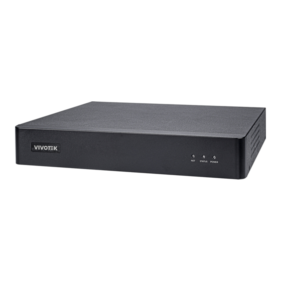
VIVOTEK - Built with Reliability Chassis Dimensions Physical Description Front View 1 2 3 1 Network uplink status/activity LED 2 System status LED 3 System power status 10 - User's Manual... - Page 11 VIVOTEK - Built with Reliability Rear View 1 PoE ports # 1 to #4 6 Audio OUT 2 RJ45 port - GbE uplink 7 VGA 3 HDMI 8 USB ports; top: 3.0, bottom: 2.0 4 Audio IN 9 Power socket (48V DC) 5 DI/DO terminal block IMPORTANT: The total power budget for the NVR’s 4 PoE ports is 50W.
- Page 12 VIVOTEK - Built with Reliability NOTE: You can also use the Reset button to restore system defaults. Press and hold down the button for longer than 5 seconds. The system should start restoring defaults. Reset button IMPORTANT: It is important to leave a clearance of 25cm behind the chassis. The clearance is required to ensure an adequate airflow through the chassis to ventilate heat.
- Page 13 VIVOTEK - Built with Reliability Hardware Installation SATA hard disk(s) are user-supplied. The network video recorder can readily accommodate most of the off-the-shelf SATA hard drives. 1. Attach 4 foot pads to the bottom of the enclosure. 2. Use a Phillips screwdriver to loosen the retention screws on the sides and the back of the chassis.
- Page 14 VIVOTEK - Built with Reliability 3. Remove the top cover. 4. Fasten 2 included screws to the bottom of your hard drive, to the 2 screw holes near the connector side. Do not completely fasten the screws yet. Leave 3 to 5mm of screw threads above the screw hole.
- Page 15 VIVOTEK - Built with Reliability 5. Connect the SATA power and SATA data cables to the hard disk drive. SATA power SATA data User's Manual - 15...
- Page 16 VIVOTEK - Built with Reliability 6. Install the hard drive to the chassis. Note that the screws pass through the bottom of the chassis and secure the hard drive using the mounting holes at the bottom of hard drives. When installing hard drives, their label side should be facing up, and the connector side fac- ing the outside of the chassis.
- Page 17 VIVOTEK - Built with Reliability When securing screws to the hard drives, do not completely fasten the screws. Fasten the screws half way and insert the screw heads into the key slot holes. When they are in place, fasten the screws from the bottom of the chassis. Bottom User's Manual - 17...
- Page 18 VIVOTEK - Built with Reliability 7. When done, install the top cover. 18 - User's Manual...
- Page 19 VIVOTEK - Built with Reliability Interface Connections 1. Connect to a monitor using an HDMI cable. VGA is also supported. 2. Connect CAT5e or better-quality Ethernet cable to the GbE Ethernet port. 3. Connect USB devices such as, mouse, keyboard, USB optical drive, or USB thumb drive (for- matted in FAT format), joystick, or UPS.
- Page 20 VIVOTEK - Built with Reliability NOTE: 1. The onboard DHCP server provides IPs for the connected PoE cameras (10.1.1.1 or 192.168.2.1 onward). The uplink Ethernet port acquires a different IP from the network it connects to. The PoE ports and the uplink are in the separated networks. If your uplink port happens to connect to a 10.1.1.x network, make sure you change your PoE subnet to 192.168.2.x segment.
- Page 21 VIVOTEK - Built with Reliability 2-6. Limitations: • When you are exporting video to the disk drives in an external storage, you cannot select the other disk drives to create a new volume. • If the disk drives or volumes in the external storage is smaller than 1TB, you cannot configure them as volumes for the NVR.
- Page 22 VIVOTEK - Built with Reliability WARNING: If you connect the NVR to a PoE port of the AW-FED series PoE switch, make sure you turn off the PoE output on that specific port using the onboard DIP switch. Otherwise, the high power output can damage the LAN port on NVR.
- Page 23 VIVOTEK - Built with Reliability Initial Configuration - via a Local Console A local console requires the following: 1. A monitor is connected via an HDMI or VGA cable. 2. A mouse and/or a keyboard are connected to the system. 3.
- Page 24 VIVOTEK - Built with Reliability IMPORTANT: Except in the initial setup, changing system time can produce disruptions to the existing recordings. Turning the current system time back to a time when video recording was taking place can generate duplicate files. And those files may not be playable. 2.
- Page 25 VIVOTEK - Built with Reliability NOTE: 1. The maximum decoding bandwidth is H.265 3840x2160@30fps 1 CH 1920x1080@120fps 4 CH H.264 3840x2160@30fps 1 CH 1920x1080@120fps 4 CH Recording throughput: 64Mbps Note that when accessed over the network, the total streaming throughput is 88Mbps. Pre-recording: 5 seconds (max.
- Page 26 VIVOTEK - Built with Reliability NOTE: If the need should arise, you can manually enter an IPv6 address to recruit a camera. Note that currently you can not search a camera with an IPv6 address in the device search panel. Note the following when using IPv6 addresses: 1.
- Page 27 VIVOTEK - Built with Reliability 4. The system will automatically create volumes from the installed disk drives. The process will take several minutes. Hard disks will be configured into single-disk volumes. You can delete these volumes and then create RAID volumes in the Settings > Storage page. 5.
- Page 28 VIVOTEK - Built with Reliability 5-2. The QR code will be generated. 5-3. Open the QR code utility from your cell phone. If you already registered an account, tap LOG IN. If not, tap SIGN UP to register an account from a VIVOTEK server. User The NVR also supports the VIVOCloud Retail app.
- Page 29 VIVOTEK - Built with Reliability 5-5. Tap the ADD DEVICES MANUALLY button. 5-6. You can then point your cell phone lens at the NVR screen (Step 5-3.) and use the SCAN QR CODES function to establish the connection. You may also manually enter the device ID.
- Page 30 VIVOTEK - Built with Reliability 5-7. The process will take several seconds to complete. 5-8. The NVR and the cameras under it will be ready for access. 6. Click the Done button. 30 - User's Manual...
-
Page 31: Led Indicators
VIVOTEK - Built with Reliability LED Indicators 1 2 3 Name Behavior Definitions 1. NET LED Blinking Green Data is being transmitted or received. The Ethernet uplink is disconnected. 2. Status LED Constant Green System ready. Blinking Green Updating firmware or device pack. every 1 second Constant 1. -
Page 32: Power Up And Power Down
VIVOTEK - Built with Reliability Power Up and Power Down To power up and power down, On the initial configuration: 1. Connect the power cord on the power adapter with the power outlet. 2. Connect the DC connecter on the power adapter to NVR's power socket. To power down, Use the Shutdown button in Settings >... - Page 33 VIVOTEK - Built with Reliability WARNING: 1. No storage system is completely fail-safe. Damage to data might occur due to file system corruption, operating system malfunction, virus infection, HDD component failures, and so on. Therefore, it is highly recommended to regularly back up your data, and VIVOTEK disclaims responsibilities of data loss or recovery.
-
Page 34: Section One Management Over A Local Console
VIVOTEK - Built with Reliability Section One Management over a Local Console Chapter Two Introduction to the Local Console Interface Camera 01 Camera 03 Camera 02 Camera 05 Camera 06 Camera 04 Camera 07 Camera 08 Camera 09 34 - User's Manual... - Page 35 VIVOTEK - Built with Reliability By default, a live view appears on an HDMI monitor. The interface architecture of the local console is illustrated as follows: LiveView Main screen Main control portals Layout Time Search panel DI/DO Alarm search Smart VCA event search Search recording clip POS search Digital zoom...
-
Page 36: How To Begin
VIVOTEK - Built with Reliability 2-1. How to Begin 1. How to access the Configuration Portal? Make sure a mouse is attached to your NVR. Move your mouse cursor, and the Configuration Portal will appear on screen. For all the configurable options available through this portal, please refer to Chapter 3 on page 49. - Page 37 VIVOTEK - Built with Reliability PTZ control panel for ordinary PTZ type PTZ control panel for joystick type PTZ Move speed config Preset points Pan/Tilt controller Focus far Focus near Zoom controller Home position Patrol button PTZ presets: If your PTZ cameras have preset locations, click on the button to unfold the preset menu.
- Page 38 VIVOTEK - Built with Reliability The Playback window will prompt, and a playback begins from the point in time you selected, e.g., 30 seconds ago. This function allows you to quickly review what has just happened. 03 - Camera 03 01 - Camera 01 2016.05.16 2016.05.16...
- Page 39 VIVOTEK - Built with Reliability 4. How to recieve system alarm? Please refer to page 103 for how to configure system alarm triggers. When the alarm is triggered, e.g., by digital inputs or motion detection, an alarm message will prompt on the screen.
- Page 40 VIVOTEK - Built with Reliability 5. Why live view is unavailable? The default live view receives a camera's stream #1. If a camera's stream #1 is configured using MPEG-4 as the video codec, the following message will prompt. You can go to the Settings > Camera > Media > Video window to configure the video codec of stream #1 into H.264 or H.265.
- Page 41 VIVOTEK - Built with Reliability 6. How do I move to another layout page? Move your cursor to the right hand side of your screen. The page turner buttons will appear as shown below. For example, if you have 8 cameras placed on 2 2x2 layout pages, use these buttons to visit different pages.
-
Page 42: Operation On Camera View Cell
VIVOTEK - Built with Reliability 2-2. Operation on Camera View Cell 2-2-1. PTZ Panel Once you selected a camera, click on the PTZ button on a camera portal. The PTZ panel will prompt. Below are the description of its functions: List of preset positions Focus far Focus near... - Page 43 VIVOTEK - Built with Reliability Below is the PTZ panel that appears with ordinary PTZ cameras. List of preset positions Speed selector Focus far Focus near Zoom in Zoom out Starts patrol 1. PTZ control: Click on the arrow buttons to move towards the direction you wish to move to.
- Page 44 VIVOTEK - Built with Reliability Joystick support The joystick related operations are listed below: 1. Pan: Continuous move is supported. (joystick X-axis movement) 2. Tilt: Continuous move is supported. (joystick Y-axis movement) 3. Zoom: Continuous move is supported. To zoom in, move joystick Z-axis clockwise (or use button #2).
-
Page 45: Digital Zoom Panel
VIVOTEK - Built with Reliability 2-2-2. Digital zoom Panel Digital zoom is a function that provides digital zoom into a live video. Be sure you place your mouse cursor inside the Global view window for the zoom function to take effect. -
Page 46: Play Recording Clips Panel
VIVOTEK - Built with Reliability 2-2-3. Play Recording Clips Panel The Play Recording Clips function provides a shortcut to the latest recordings on the system. You can select 30 secs, 1 min, 3 mins, 10 mins, and 60 mins for an immediate playback. -
Page 47: Di/Do
VIVOTEK - Built with Reliability 2-2-4. DI/DO The DI/DO panel provides a glimpse of all DI and DO signal statuses from the connected cameras. You can manually trigger a digital output by clicking on its indicators. When a digital input is triggered, its status will also be indicated on the panel. -
Page 48: Right-Click Commands
VIVOTEK - Built with Reliability 2-2-6. Right-click Commands Left-click to select a camera. Right-click to display the selection menu. 1. Camera information: Click to display camera name, resolution, codec, or frame rate on the view cell. The information will display on the upper left corner of a view cell. 2. -
Page 49: Chapter Three Configuation Using The Local Console
VIVOTEK - Built with Reliability Chapter Three Configuation Using the Local Console The Main Control Portal 3-1. Layout Move your mouse cursor across the screen to display the portal. The local layouts: 1x1, 2x2, 3x3, 1M+5, 1P+3, 1P+6, 2P+3, 3V If you select the single view layout, the rotation button will appear. -
Page 50: Search Recording Clips
VIVOTEK - Built with Reliability 3-3. Search recording clips 3-3-1. Basic Search Click the button to start searching for recorded clips. A confirm box will prompt. Enter User name and Password to proceed. The search and calendar view will appear. Select a day on the calendar to select the date when the recordings of your interest took place (the days with recorded clips will be highlighted in blue and green). - Page 51 VIVOTEK - Built with Reliability The timeline bar enables quick skimming through the recording. Its functions are described as follows: Control buttons Functional buttons Timeline scale Span of existing Current time recording indicator Buttons Description Time scale selector. Use the buttons to select the span of time displayed on the tool bar.
- Page 52 VIVOTEK - Built with Reliability Note that to export a video segment from the playback timeline, 1. Click on the Export button 2. Insert a USB drive formatted in the FAT format. 3. Select the "From time" by clicking on the timeline. You can also manually enter the "From time"...
-
Page 53: Alarm Search
VIVOTEK - Built with Reliability 3-3-2. Alarm Search Click on the Alarm search button on the upper left of the screen to enter the Alarm Search panel. You can specify the search criteria by selecting the devices to be involved in the Alarm search. 1. - Page 54 VIVOTEK - Built with Reliability You can then specify the start time and end time to configure a span of time to be searched. You can also determine what alarms will be included in the search. 54 - User's Manual...
- Page 55 VIVOTEK - Built with Reliability You can select what types of triggers were associated with the recordings you want to find. When done with the selection, click on the Search button. In the sample screen below, a list of alarms is displayed, and you can click on any of them to replay the moment when the alarm was triggered.
- Page 56 VIVOTEK - Built with Reliability Use the page up and page down buttons to browse through the alarm list. Use the continuous playback button to let the system automatically play all alarm clips. The continuous play starts from the first alarm or from the alarm you currently clicked and selected. Click on the button again to stop the continuous play.
-
Page 57: Pos Search
VIVOTEK - Built with Reliability 3-3-3. POS Search Search by POS transaction: The NVR station can collect coordinated database information from a POS machine. This function provides access to the video clips associated with the sales records on the POS machine. Details of transaction can be listed on screen so that a manager can see the live view when controversial events occur. - Page 58 VIVOTEK - Built with Reliability 6. You can click on any of the search results to display the transaction data or playback the associated video. Displays Playback transaction data 7. You can export the related video if the need should arise. Make sure you select the "Include POS transaction data"...
- Page 59 VIVOTEK - Built with Reliability 8. Once exported, you should contact VIVOTEK's technical support for a custom-made StandalonePlayer. Copy the standalone player to the same folder of your exported video. Use it to playback the exported video. 9. The transaction details will display along with the exported video. User's Manual - 59...
-
Page 60: Smart Vca Event Search
VIVOTEK - Built with Reliability 3-3-5. Smart VCA event search This search panel enables the search for the detection results from Smart VCA analytics functions. They include: * Line crossing detection * Intrusion detection * Loitering detection * Face detection * Missing objection detection * Unattended object detection * Crowd detection... - Page 61 VIVOTEK - Built with Reliability Below are the short introductions to these analytics functions: Line Crossing Detection The Line Crossing detection detects one or multiple persons crossing a virtual trip-wire. The traffic direction can be assigned on screen for persons passing the line in one specific direction or in both directions.
- Page 62 VIVOTEK - Built with Reliability Loitering Detection The Loitering detection can be used to detect a person of a group of people lingering in an area for longer than a preset time threshold. The applicable scenarios of this feature can be: * Detects when a pserson is loitering at a walk-up of ATM lane.
- Page 63 VIVOTEK - Built with Reliability Unattended Object Detection The Unattended Object detection can be used to detect objects intentionally or unintentionally left in scene. The applicable scenarios of this feature can be: * Detects objects placed in front of an emergency exit. * Detects objects left on subway tracks, platform, on a bridge, or in a bank lobby.
- Page 64 VIVOTEK - Built with Reliability Crowd Detection Crowd detection calculates the number of people in a specific area. When the number exceeds a preset number, an event is triggered. The applicable scenarios of this feature can be: * Detects the congestion when the number of people in a region exceeds a preset number, e.g., 10 in a waiting line.
- Page 65 VIVOTEK - Built with Reliability The Smart VCA search function can be accessed from the main portal using the Search button. When you are at the search panel, click on the Smart VCA search tab. 1. Select the cameras that generate VCA events. Select at least one camera. 2.
- Page 66 VIVOTEK - Built with Reliability 5. The search results will display as thumbnail images. To view each short video clip, click on the thumbnail. The playback video window is located on the right. Click on the Expand/Shrink button to watch the video in a full screen. You can use the Esc button to leave the full screen.
- Page 67 VIVOTEK - Built with Reliability You may use the sort menus on the upper right to sort your search results. If using the "Sort by event type" option, events of different types will be displayed in a successive order. When exporting video clips, mouse over and select the small checkboxes on the thumbnails. Single-click to select video clips.
-
Page 68: Storyboard
VIVOTEK - Built with Reliability 3-3-6. Storyboard The Storyboard interface provides a glimpse of past recordings over a timeline. It looks and operates like doing the film editing after a film was shot. To enter the Storyboard window, click on the Storyboard shortcut on the upper-left of screen. Below are the screen elements of the Storyboard window: Camera selector Time selector... - Page 69 VIVOTEK - Built with Reliability Mouse over the line of snapshots to display its time of recording. Click on a snapshot of your interest. The time of recording is immediately displayed on top of it. The detailed search is based on a narrow-down criteria. The search begins from a 24-hour time span, and then moving in to a 4-hour, 1-hour, 10-minutes, and 2-minutes span.
- Page 70 VIVOTEK - Built with Reliability If you find yourself in the wrong segment on the timeline, use the buttons on the upper-right of the screen to travel. The definitions of these buttons depend on the time span of your current position. For example, if you are in a 4-hour time span, the "Back to previous state button"...
- Page 71 VIVOTEK - Built with Reliability The playback window will appear. Please refer to page 51 for the operation details. 01-01 camera 2016.03.14 14:05:09 To return to the Live View window, click on the Back to Search recording clips button the Back to Liveview button on the upper-left of the screen.
-
Page 72: Export Recordings
VIVOTEK - Built with Reliability 3-4. Export recordings The Export recordings button allows users to directly select a piece of recordings by a specific camera, and export that to a USB thumb drive. Users can select one or multiple cameras, select a period of time in which the recording took place, and then click export. - Page 73 VIVOTEK - Built with Reliability 6. The Export progress will be shown. 7. When the Export process is done, select to resume another export or go back to the live view. Note that the Export process can take a long time if the time span of the selected video is very long.
-
Page 74: Settings
VIVOTEK - Built with Reliability 3-5. Settings 3-5-1. Settings - Overview Click the Settings button to start the camera and system settings window. A confirm box will prompt. Enter User name and Password to proceed. The system will default to the overview page displaying the camera connection and storage statuses. -
Page 75: Settings-Camera-Management
VIVOTEK - Built with Reliability The Camera menu provides access to Management, Recording, Media, Image, Motion detection, and PTZ settings pages. 3-5-2. Settings–Camera–Management On the camera Management page, you can configure the following: 1. Recruit or disband cameras. 2. Create a camera name. 3. - Page 76 VIVOTEK - Built with Reliability For legacy cameras, the NVR supports RTSP connections since firmware release revision 2.6.x. To manually add a legacy camera, 1. Select an empty camera entry, 2. Click the Add button, 3. Select RTSP as the protocol. 4.
- Page 77 VIVOTEK - Built with Reliability In Media > Stream managemeent page, the related Video, Audio, and stream configuration for RTSP cameras can not be edited. The RSTP cameras will be tagged. User's Manual - 77...
- Page 78 VIVOTEK - Built with Reliability To recruit cameras: 1. Click on the Add button. A list of cameras in the same subnet will appear. 2. Click the Add button, the camera will be placed at an unoccupied position. You may also expand the menu on the side of the Add button to select a position number.
- Page 79 VIVOTEK - Built with Reliability To disband cameras: 1. Click on the Remove button. A list of cameras will appear. 2. The Remove button will turn yellow . Mouse over to the camera you want to remove, and its entry will display the Remove message. 3.
- Page 80 VIVOTEK - Built with Reliability Network On the Network tabbed window, you can configure the network type, IP address, and the connection ports for video streaming. The cameras connected to the NVR PoE ports are placed behind a default gateway 10.1.1.1 or 192.168.2.1. You can select DHCP as the method for cameras to acquire IP addresses, or you can manually configure static IPs for a single or all cameras.
- Page 81 VIVOTEK - Built with Reliability Camera position To change a camera's position on the Liveview layout, click and drag a camera to an unpopulated position. Note that you cannot swap the positions of two cameras by dragging a camera onto a position already populated by the other. Also, the camera index number on the management list is not affected by the change of positions.
-
Page 82: Settings-Camera-Recording
VIVOTEK - Built with Reliability 3-5-3. Settings–Camera–Recording Recording options On the camera Recording page, you can configure the following: 1. Configure the duration of camera events, for the concern that camera can be too frequently triggered. 2. Enter the Pre- and Post-event recording time. The triggering events can be DI, DO, Motion detection, PIR, or Tampering detection. -
Page 83: Settings-Camera-Recording
VIVOTEK - Built with Reliability 7. Watermark password: Configure a password in a length of 16 to 64 characters. You can use it to verify the authenticity of exported videos using the included video player. Select File > Verify Watermark. Enter the password to verify. - Page 84 VIVOTEK - Built with Reliability Recording Schedule By default, all video feeds from cameras are recorded at all time. You can modify the recording task using the schedule tool: 1. Click to select a recording condition's checkbox–1. Continuous recording , Event recording , and 3.
-
Page 85: Settings-Camera-Media
VIVOTEK - Built with Reliability 3-5-4. Settings–Camera–Media The NVR automatically changes camera stream settings when cameras are added. If users want to manually configure camera stream setting, they can disable this function. The default for the automatic configuration is, • Main stream: H.265 1080p •... - Page 86 VIVOTEK - Built with Reliability The NVR adaptively selects to display a video stream of a different resolution when it is displaying on a smaller view cell or a full screen. By default, the Recording stream is Main Stream, which is recorded to the H.D.D. 86 - User's Manual...
- Page 87 VIVOTEK - Built with Reliability Video The Video window allows you to configure all video streams (the no. of stream available can be different for different models). You can configure the following: 1. Main stream/ Sub stream: Select to configure two basic categorized streams. 2.
- Page 88 VIVOTEK - Built with Reliability ■ Dynamic Intra frame period High quality motion codecs, such as H.265, utilize the redundancies between video frames to deliver video streams at a balance of quality and bit rate. The encoding parameters are summarized and illustrated below. The I-frames are completely self- referential and they are largest in size.
- Page 89 VIVOTEK - Built with Reliability Smart codec effectively reduces the quality of the whole or the non-interested areas on a ■ screen and therefore reduces the bandwidth consumed. You can manually specify the video quality for the foreground and the background areas. Slide bar to the right - higher quality in the ROI areas Slide bar to the left - higher quality in the non-ROI...
- Page 90 VIVOTEK - Built with Reliability As the result, the lower screen is constantly displayed in high details, while the upper half is transmitted using a lower-quality format. Although the upper half is transmitted using a lower quality format, you still have an awareness of what is happening on the whole screen.
- Page 91 VIVOTEK - Built with Reliability Audio The Audio window allows you to configure all audio codec, sampling rate, and Microphone input gains. Depending on design of the camera models, some codecs may not be available. Also, there are cameras that come without embedded mircrophones. User's Manual - 91...
-
Page 92: Settings - Camera - Image
VIVOTEK - Built with Reliability 3-5-5. Settings - Camera - Image Display The Display window allows users to tune the image display options: 1. Video name: the video name is displayed on the title bar that is displayed on each view cell. - Page 93 VIVOTEK - Built with Reliability Day/Night settings Switch to B/W in night mode Select this checkbox to enable the Network Camera to automatically switch to Black & White display during the night mode. IR cut filter With a removable IR-cut filter, this Network Camera can automatically remove the filter to let Infrared light pass into the sensor during low light conditions.
- Page 94 VIVOTEK - Built with Reliability Image settings The Image adjustment window allows users to tune the basics about image display options: 1. Color: Select to display image as color or black and white. 2. Brightness. 3. Saturation. 4. Contrast. 5. Sharpness. 6.
- Page 95 VIVOTEK - Built with Reliability Exposure: Enable WDR Pro: This refers to the Wide Dynamic Range function that enables the camera to capture details in a high contrast environment. Use the checkbox to enable the function, and use the slide bar to select the strength of the WDR Pro functionality, depending on the lighting condition at the installation site.
- Page 96 VIVOTEK - Built with Reliability Focus: Enable WDR Pro: This refers to the Wide Dynamic Range function that enables the camera to capture details in a high contrast environment. Use the checkbox to enable the function, and use the slide bar to select the strength of the WDR Pro functionality, depending on the lighting condition at the installation site.
-
Page 97: Settings-Camera-Motion Detection
VIVOTEK - Built with Reliability 3-5-6. Settings–Camera–Motion Detection Motion Detection To set up a detection window: 1. Select a camera by a single click. 2. Use the PTZ panel to move to a field of view where you want to place a detection window. -
Page 98: Settings - Camera - Ptz Settings
VIVOTEK - Built with Reliability 3-5-7. Settings - Camera - PTZ settings To configure PTZ preset positions: 1. Select a PTZ camera by a single click. 2. Use the PTZ panel to move to a field of view where you want to designate as a preset position. - Page 99 VIVOTEK - Built with Reliability To configure a patrol: 1. Click to enter the Patrol menu. Select a preset position if you want to change its position on the patrolling order. 2. Click the up and down buttons to change the position on the order, or click the remove button to disband a position from the order.
-
Page 100: Settings - Camera - Port Forwarding
VIVOTEK - Built with Reliability 3-5-8. Settings - Camera - Port forwarding You can associate an external port number to the cameras managed by the NVR. You can then configure the router, virtual server or firewall, so that the router can forward any data coming into a pre-configured port number to a network camera on the private network, and allow data from the camera to be transmitted to the outside of the network over the same path. -
Page 101: Settings - Camera - Update Firmware
VIVOTEK - Built with Reliability 3-5-9. Settings - Camera - Update firmware Prepare the camera firmware files in a USB thumb drive. Connect the thumb drive to the NVR’s USB port. Select a camera, and click the upload button. An upload panel will appear. Select the firmware file. Click the Upload button. User's Manual - 101... - Page 102 VIVOTEK - Built with Reliability The Batch upload function allows you to update the firmware of multiple cameras. The firmware update can take place on up to 8 cameras at a time. The Waiting... message will display for cameras that are waiting for the update to take place. Different messages can appear with different update results.
-
Page 103: Settings-Alarm-Alarm
VIVOTEK - Built with Reliability 3-5-10. Settings–Alarm–Alarm The events reported from individual cameras' digital inputs, digital outputs, and motion detection can be accommodated in the NVR system's alarm settings. These events will then be reported or trigger corresponding actions as follows: 1. - Page 104 VIVOTEK - Built with Reliability When an alarm is triggered, a message prompt will appear on the Liveview or any configuration window. Below is a glimpse of alarm sources and alarm actions: Sources Actions System DI Video recording ►video footage System DO Send Email ►snapshots...
- Page 105 VIVOTEK - Built with Reliability To create an alarm, 1. Click on the Add button You can manually enter a name for the current setting. You can enter up to 16 numeric or alphabetic characters for the name, including symbols such as [0-9][a-z][A-Z][_][ ]. You can also designate the interval between one alarm and the next triggered alarm to avoid the situation that the alarms can be too frequently triggered.
- Page 106 VIVOTEK - Built with Reliability 3. On the Trigger window, select system triggering conditions, or one or more cameras by selecting their checkboxes. The number of DI or DOs on each camera is automatically detected and displayed through individual checkboxes. The Motion detection function, if there are many detection windows configured on a camera, is all triggered by one checkbox.
- Page 107 VIVOTEK - Built with Reliability 4. On the Action window, you can select the Action type from a drop-down menu. The configuration details of each action type is discussion below. 4-1. Recording–When an event is triggered, the selected camera will record a video footage of the length defined by the pre-/post-event setting, to the NVR system.
- Page 108 VIVOTEK - Built with Reliability The Email subject and addresses can be composed of 254 characters in numeric or alphabetic characters including: [0-9][a-z][A-Z][_][ ][-][.][,][@]. You can enter the addresses of multiple recipients. Use semicolons, (;), to separate the addresses of multiple recipients. 4-3.
- Page 109 VIVOTEK - Built with Reliability 4-4. FTP–Snapshots from specified cameras can be uploaded to an FTP site on the occurrence of an event. Enter the FTP site address in the dotted-decimal notation, e.g., 159.22.151.20. Enter the login name and password for the user account. You can enter a directory name you prefer on the FTP site.
- Page 110 VIVOTEK - Built with Reliability 4-5. Camera DO - A triggered alarm triggers a camera's DO, e.g., an alarm siren. 4-6. Camera pan-tilt-zoom - A PTZ capable camera can move its lens to the preset position in case of a triggered alarm. For example, a triggered sensor may indicate an area of interest has been intruded, and a camera's field of view should be moved to cover that area.
- Page 111 VIVOTEK - Built with Reliability 4-7. System DO - A triggered alarm can be used to toggle the NVR's digital output, e.g., to sound an alarm siren. 4-8. VIVOCloud app notification - A triggered alarm can be used to toggle an event notification to the VIVOCloud utility.
- Page 112 VIVOTEK - Built with Reliability 4-9. Send to CMS–An event message will display on your VAST CMS software in the event of GPS signal loss or G-sensor force exceeds configured thresholds. The triggered alarms can be found in the Alarm search panel. 112 - User's Manual...
- Page 113 VIVOTEK - Built with Reliability You should also configure a corresponding alarm on the VAST server. Enter the Alarm management window. Select System Event and begin your configuration. Select NVR and a triggering condition, such as the GPS diconnect, as your trigger. User's Manual - 113...
- Page 114 VIVOTEK - Built with Reliability Select the triggering condition from the pull-down menu. Configure the corresponding action, and proceed with the rest of the configuration. When an event is triggered, such as GPS signal loss, or exceptional G-force is detected, an event message will prompt on screen.
- Page 115 VIVOTEK - Built with Reliability 4-10. Send video to full screen–The video feed from a related camera will be displayed on the occurrence of a triggered condition. 5. On the Schedule page, you can select to activate or de-activate alarm triggers throughout a specific timeline.
-
Page 116: Settings - Alarm - Email
VIVOTEK - Built with Reliability 3-5-11. Settings - Alarm - Email This window provides an interface where you can configure the connection to a Mail server. Via the Mail server, the system can deliver Emails containing system alarm messages to multiple receivers. -
Page 117: Settings-System-Information
VIVOTEK - Built with Reliability 3-5-12. Settings–System–Information On this window, you can configure the following: 1. Change the system name. Using a name in different languages is supported via a web console. 2. Select the UI text language. 3. Configure system time, time zone, and if you are connected to a DNS server where Auto Daylight Saving time can be applied, you can acquire the associated setting from a server within your network. -
Page 118: Settings-System-Maintenance
VIVOTEK - Built with Reliability 3-5-13. Settings–System–Maintenance If the need arises for updating system firmware, acquire the update from VIVOTEK's technical support or download site. Locate the firmware binaries, and click the Import button. The upgrade should take several minutes to complete. Note that during the upgrade, the recording task will be interrupted. -
Page 119: Settings - System - Display
VIVOTEK - Built with Reliability 3-5-14. Settings - System - Display On this page, you can configure the system to consecutively display (rotate) cameras' view cells on the Liveview window. For example, if you have 8 cameras in 2 2x2 layouts, the rotation can let you see the live views of all cameras by every few seconds. -
Page 120: Settings - System - Poe Management
VIVOTEK - Built with Reliability 3-5-15. Settings - System - PoE management When IP cameras are connected to the NVR's PoE ports, their power consumption is constantly monitored, and the power budget is displayed on the PoE management screen. The following apply to the PoE connections and PoE management: 1. - Page 121 VIVOTEK - Built with Reliability 9. The PoE automatic enlistment does not apply for cameras that come with preset credentials, namely, password-proteced. 10. The PoE port status can reflect the following situations: A. PoE enable –PoE is working (port icon displayed in green on the upper-right screen) B.
-
Page 122: Settings - System - Ups
VIVOTEK - Built with Reliability 3-5-16. Settings - System - UPS On this page, you can configure the system to gracefully shut down when UPS battery is lower than a certain level. You may also let it shut down when the estimated sustainable time is reached. -
Page 123: Settings - System - Log
VIVOTEK - Built with Reliability 3-5-17. Settings - System - Log System logs are categorized as System, Recording, User, and Error. To display system logs, select a range of time and click on the Search button. You can search for past logs in each category window. User's Manual - 123... - Page 124 VIVOTEK - Built with Reliability 124 - User's Manual...
-
Page 125: Settings - System - Vivocloud Service
VIVOTEK - Built with Reliability 3-5-18. Settings - System - VIVOCloud service This window provides access to the VIVOCloud configuration. Please refer to page 27 for how to configure system access using the VIVOCloud functionality. User's Manual - 125... -
Page 126: Settings - System - Customer Support
VIVOTEK - Built with Reliability 3-5-19. Settings – System - Customer support If users encounter problems with the system, they could export a debug report and send it to VIVOTEK's technical support. With an Internet connection, users can also open the Remote access functionality. An access ID will be generated. -
Page 127: Settings-User
VIVOTEK - Built with Reliability 3-5-20. Settings–User The User window allows you to create more users, to change user password, and place limitations on users' privileges and administration rights. Up to 16 users can be created, including the default administrator. 1. - Page 128 VIVOTEK - Built with Reliability To create or edit users, 1. Select a User group by unfolding its pull-down menu. Select either an Administrator or regular user as the user group. 2. Enter the User name and password. The max. number of characters for a user name is 64, with alphabetic and numeric characters including [0-9][a-z][A-Z][_][ ][-][.][,][@].
-
Page 129: Settings-User-Login / Logout
VIVOTEK - Built with Reliability 3. If you are creating a regular user with limited access to cameras, deselect the checkboxes by the cameras to deny the user access. 4. Click Apply to close the configuration window. Repeat the process to create more users. 3-5-21. -
Page 130: Settings-Storage
VIVOTEK - Built with Reliability 3-5-22. Settings–Storage The storage page displays the volume information including physcial position, total capacity, used and free space, and associated commands such as Format and Delete. Since each volume contains only 1 hard drive, detailed information about the hard drive is also displayed on this page. - Page 131 VIVOTEK - Built with Reliability Attribute: The various attributes can vary from different HDD manufacturers. Value: Value for the currently selected attribute. Worst: Worst value acquired for that attribute. Threshold: A predefined threshold or triggering value. The threshold below which the normalized value will be considered exceeding specifications.
- Page 132 VIVOTEK - Built with Reliability On this configuration window, a "disk" refers to a physical disk drive, a "volume" refers to the logical configuration of disk drives which may include multiple disk drives. IMPORTANT: There are conditions that disk drives will not be available for storage configuration: 1.
-
Page 133: Settings - Storage - Scheduled Backup
VIVOTEK - Built with Reliability 3-5-23. Settings - Storage - Scheduled backup To configure a scheduled backup, 1. Select the Scheduled backup: Enable checkbox. 2. Server: Enter the server name or IP address of the FTP server. 3. Port: Enter the port number. Default is 21. 4. - Page 134 VIVOTEK - Built with Reliability Enable: Default is not selected. The scheduled backup function is not enabled by default. You must click to enable the configuration options. Type: Currently the NVR supports the backup to an FTP server. Enter the Static IP, domain name, and other parameters for access to an FTP server. Site: the fully qualified domain name of a network host, or its IP address.
- Page 135 VIVOTEK - Built with Reliability When finished with the network settings, click on the Apply button. A proceeding backup can be manually cancelled. User's Manual - 135...
-
Page 136: Settings - Network
VIVOTEK - Built with Reliability 3-5-24. Settings - Network Settings - Network - IP DHCP: Default is selected, the server obtains an available dynamic IP address assigned by the DHCP server each time the system is connected to the LAN. Manual setup: Select this option to manually assign a static IP address to the NVR. -
Page 137: Settings - Ddns
VIVOTEK - Built with Reliability Settings - DDNS VIVOTEK provides Safe100.net, as a free DDNS dynamic domain name service for users who want access from the internet or a domain name service for the NVR. VIVOTEK maintains a database of product MAC addresses for the Safe100.net service, and you can apply one domain name for each NVR system. -
Page 138: Settings-Service
VIVOTEK - Built with Reliability Settings–Service By default, the NVR service and video streaming are accessed via HTTP port 80 and RTSP port 554. You can designate a different port number if the need arises. Usually it is not necessary to change these ports. - Page 139 VIVOTEK - Built with Reliability VAST2 auto connection NAT-traversal with OpenVPN You can select the "VAST Server with OpenVPN" option when installing the VAST server. A remote connection from NVR via a 3G/4G/LTE network can be made through an OpenVPN tunnel. When the OpenVPN option is selected, an OpenVPN server will be installed with the VAST server.
- Page 140 VIVOTEK - Built with Reliability With a remote VAST2 instance that needs to access the NVR via the Internet, you can enter its public IP address and credentials. The NVR runs an Open VPN client that makes remote connection via the RESTful (Repretational State Transfer) API (Application Programming Interface) service to a VPN server running on the remote site.
- Page 141 VIVOTEK - Built with Reliability Note that the NVR and VAST server should have a similar time setting when exchanging certificate information. Otherwise, the mutual handshake authentication process may fail. Enter the OpenVPN DNS domain name and the credentials on the NVR network service configuration page.
-
Page 142: Pos
VIVOTEK - Built with Reliability 3-6. POS This window allows the integration of a customized POS machine with the NVR. The benefits of NVR POS integration benefits include: 1. POS exception report that includes item void, bill void, abnormal bill clear, customer returns, contents changed after sale, unmatched amount of products in stock, unusual transactions in a short time, aborted bill attempts. - Page 143 VIVOTEK - Built with Reliability For example, for an amount exceeding $2000, the number on screen is highlighted in a different color. To allow remote access from a VAST server, go to Settings > Service. Select the Allow access checkbox and provide a CMS password to allow remote access. User's Manual - 143...
-
Page 144: Information
VIVOTEK - Built with Reliability 3-8. Information This window shows the revision number of the firmware running on this machine. 144 - User's Manual... -
Page 145: Section Two Management Over A Web Console
VIVOTEK - Built with Reliability Section Two Management over a Web Console Below are the requirements for using a web console: 1. i5 CPU or above with a minimum of 8GB RAM. 2. It is recommended to configure a sub stream in H.264, with a lower resolution of 640 x 360. 3. -
Page 146: Chapter Four Login And Getting Started
VIVOTEK - Built with Reliability Chapter Four Login and Getting Started 4-1. Login This is the login page on the browser. The minimum for resolution is 1280x960. Pleae use Google Chrome to access the NVR. By default, the web console opens with the new user interface. - Page 147 VIVOTEK - Built with Reliability Remember me: Your user name will be preserved in browser cookies for two days if you select the Remember me checkbox. The user name will be automatically erased if you do not log in to the system for two days.
- Page 148 VIVOTEK - Built with Reliability Login options: You may also mouse over the Login button to display the login options. You can then enter the Liveview, Playback, or Alarm search window. The NVR system features a simple UI structure which consists of a Liveview window, a Playback utility, and a system Settings window.
- Page 149 VIVOTEK - Built with Reliability NOTE: The NVR supports plug-in-free web sessions using Chrome browsers. IMPORTANT: 1. Before operating the NVR, make sure you have properly installed hard drives and configured the storage volumes. Otherwise, you will not be able to operate some of the system's functionality.
-
Page 150: Graphical Layout And Screen Elements - Liveview
VIVOTEK - Built with Reliability 4-2. Graphical Layout and Screen Elements - Liveview Storage Viewcell panel Notification Login / Log out Date & Time Live view Playback Search Settings Device list Control & Display Pane Shrink/Expand Shrink/Expand Layout Full screen Page changer Rotation mode Once you log in, the system defaults to the Liveview page, which provides access to other... -
Page 151: Device List Panel
VIVOTEK - Built with Reliability Item Name Description Page changer Cick to move to the other layout page when your live views are distributed over many pages. Full screen Enters the full screen with only the live views. Each panel will be described in further discussions. 4-2-1. - Page 152 VIVOTEK - Built with Reliability Once devices are added to the NVR, they will be listed. The device type will be automatically detected. Different types of devices will be given different types of device icons. Recording is taking place Device name Device index Type icon Different types of devices will be given different types of device icons.
- Page 153 VIVOTEK - Built with Reliability User's Manual - 153...
-
Page 154: Layout
VIVOTEK - Built with Reliability 4-2-2. Layout 1M+5 1M+7 1P+3 1P+6 2P+3 1V+6 2V+3 Only an administrator can change and preserve a custom layout, and every user can designate a specific layout to be displayed when he/she logs in. The default layout for each user is stored in a browser's cookies. -
Page 155: Scene
VIVOTEK - Built with Reliability 4-2-3. Scene A scene allows users to gather the live views from multiple cameras together into a comprehensive glimpse of view. For example, several cameras may have been installed to cover a specific area. To create a new scene, click on the Create scene button. You can change layout, enter a name for the new scene, and click and drag cameras into the layout. -
Page 156: View Cell Panel
VIVOTEK - Built with Reliability 4-2-5. View Cell panel A single view cell is shown below. Each view cell contains a video stream display area, information, and functional buttons. A view cell is displayed in Normal, Focused, or Maximized mode. 1. - Page 157 VIVOTEK - Built with Reliability Sometimes network problems can cause a view cell to be attempting to connect to a network camera. If the connection attempt takes a long time, it may result from network problems or incorrect configuration with video streaming. For example, you may have configured the camera to be streaming a 5MP stream.
- Page 158 VIVOTEK - Built with Reliability Control Pane Click to select any of the view cells to activate its Control and Display panes. You can exert the following: 1. View basic information such as the IP address, Model name, etc. 2. Start a manual recording. 3.
- Page 159 VIVOTEK - Built with Reliability * For a fisheye camera, you can select a dewarp mode as a Regional view or a Panoramic view. 1O View (Original View) 1O (Original view) 180° Hemispheric 1P (Panoramic view) Swipe to scroll horizontally User's Manual - 159...
- Page 160 VIVOTEK - Built with Reliability 1R (Regional view) 1R View (Single Regional View) Zoom Out Zoom In Zoom in/out & all-directional navigation control The 1R mode (or rectilinear) provides access to one image section within the hemisphere. You can zoom in or out (using the mouse wheel or PTZ panel) or travel through to other areas within the hemisphere using simple mouse clicks and drags.
- Page 161 VIVOTEK - Built with Reliability * For a PTZ camera, scroll down to display the PTZ control panel where you can zoom, focus, pan, patrol, or move the camera lens. On a live view of a PTZ camera, you can hold down the mouse button and move the cursor towards the direction you want to move.
- Page 162 VIVOTEK - Built with Reliability Display Pane On the Display pane, you can configure the following: 1. Enable or disable the display of the Camera type, the small icon on the upper left of view cell. 2. Camera name and IP address. Select one or both. 3.
-
Page 163: Graphical Layout And Screen Elements - Playback
VIVOTEK - Built with Reliability 4-3. Graphical Layout and Screen Elements - Playback Camera list Calendar Playback panel Layout contents The screen elements of the Playback window are described as follows: Item Name Description Camera List Provides a glimpse of all cameras that have recorded data. Basic information is also provided along with a screenshot. -
Page 164: Playback Panel
VIVOTEK - Built with Reliability Playback Panel Timeline slider Control buttons Span of existing recording Timeline zoomer The time slide bar enables quick skimming through the recording. Its functional buttons are described as follows: Buttons Description Pause Play. This button is available after you manually pause a playback. Next frame. - Page 165 VIVOTEK - Built with Reliability When you find something of your interest, use the Export function to export a video clip. Select the length of the video clip using the Start and Stop time menus below. Depending on the length of clips, an export can take a while to finish. The default export length is 30 minutes.
-
Page 166: Graphical Layout And Screen Elements - Search
VIVOTEK - Built with Reliability 4-4. Graphical Layout and Screen Elements - Search Search conditions Calendar Playback button Configured alarms Trigger types Search results The screen elements of the Playback window are described as follows: Item Name Description Search The whole panel provides access to search conditions. You can select Devices, conditions time span, pre-configured alarms, or trigger types. - Page 167 VIVOTEK - Built with Reliability To begin playback and search for past recordings, 1. Single click to select a camera. You can select multiple cameras. 2. The Calendar panel will display the days video recording actually took place. And those days will be highlighted by a lighter text.
-
Page 168: Chapter Five System Settings
VIVOTEK - Built with Reliability Chapter Five System Settings The System Settings pages are made identical to those on the local console. Since the Setting pages are identical, the following pages will be omitted. Please refer to page 74 for the description of System Settings via a local console. - Page 169 VIVOTEK - Built with Reliability Another difference is the ability to enter a camera or system name using languages other than English. The NVR's system name also supports the use of other lanaguages. This is only achievable through a web console. The following characters are not supported: [>][<][)][(]["][%][;][#][&][+][-][\] User's Manual - 169...
-
Page 170: Safety And Compatibility
VIVOTEK - Built with Reliability Safety and Compatibility Federal Communications Commission (FCC) Statement This Equipment has been tested and found to comply with the limits for a Class A digital device, pursuant to Part 15 of the FCC rules. These limits are designed to provide reasonable protection against harmful interference when the equipment is operated in a commercial environment. - Page 171 VIVOTEK - Built with Reliability Technology License Notice Notices from HEVC Advance: THIS PRODUCT IS SOLD WITH A LIMITED LICENSE AND IS AUTHORIZED TO BE USED ONLY IN CONNECTION WITH HEVC CONTENT THAT MEETS EACH OF THE THREE FOLLOWING QUALIFICATIONS: (1) HEVC CONTENT ONLY FOR PERSONAL USE; (2) HEVC CONTENT THAT IS NOT OFFERED FOR SALE;...
Need help?
Do you have a question about the Vivotek ND9213P and is the answer not in the manual?
Questions and answers