Advertisement
Available languages
Available languages
Quick Links
Quick Start Guide
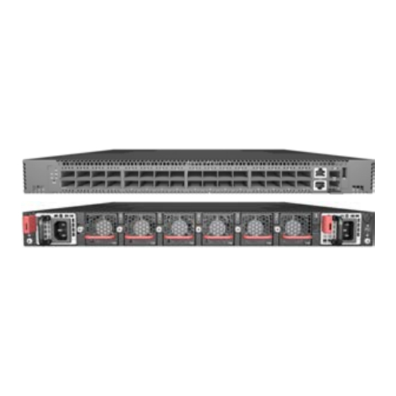
32-Port 100G Top-of-Rack Switch
F9432-C | F9432B-C
1.
32-Port 100G Top-of-Rack Switch F9432-C
2.
Rack mounting kit—2 front-post brackets, 2 rear-post brackets,
20 screws, and 2 ear-locking screws
3.
Power cord (included with AC PSUs only)
4.
Ground wire (included with DC PSUs only)
Warning:
For a safe and reliable installation, use only the
accessories and screws provided with the F9432-C. Use of other
accessories and screws could result in damage to the unit. Any
damages incurred by using unapproved accessories are not
covered by the warranty.
Avertissement:
Pour une installation sûre et fiable, utilisez
uniquement les accessoires et les vis fournies avec le F9432-C.
L'utilisation d'autres accessoires et vis pourrait endommager
l'appareil. Les dommages causés par l'utilisation d'accessoires
non approuvés ne sont pas couverts par la garantie.
Caution:
The switch includes plug-in power supply (PSU)
and fan tray modules that are installed into its chassis. All
installed modules must have a matching airflow direction.
That is, if the installed power modules have a front-to-back
(F2B) airflow direction, all the installed fan tray modules
must also have a F2B airflow direction.
Attention:
Le commutateur comprend des modules
d'alimentation et de bac de ventilateurs installés sur son
châssis. Tous les modules installés doivent avoir une direction
de circulation d'air correspondante. C'est-à-dire que tous les
modules doivent avoir la même direction de circulation d'air
: avant vers arrière (F2B), ou arrière vers avant (B2F).
Note:
The switch has the Open Network Install Environment
(ONIE) software installer pre-loaded on the switch, but no
switch software image. Information about compatible switch
software can be found at
www.edge-core.com.
1
Attach the Brackets
2
1.
Attach each of the front- and rear-post brackets to the switch using
four of the included bracket screws.
2.
Use the screws and cage/clip nuts supplied with the rack to secure
the switch in the rack.
www.pluribusnetworks.com
Package Contents
1
2
1
1
3
4
5.
Console cable—RJ-45 to DB-9
6.
DC power connector (included with 48 VDC PSU only)
7.
Documentation—Quick Start Guide (this document) and Safety
and Regulatory Information
Caution:
Installing the switch in a rack requires two people.
One person should position the switch in the rack, while the
other person secures it using the rack screws.
Attention:
Deux personnes sont nécessaires pour installer un
commutateur dans un bâti : La première personne va
positionner le commutateur dans le bâti, la seconde va le fixer
avec des vis de montage.
2
Adjust Rear-Post Bracket Ears
1.
Lock the position of the rear-post bracket ears using the included
position-locking screws.
You can adjust the rear-post bracket ears to fit different rack depths
from 56 cm to 75 cm.
3
Ground the Switch
1
1.
Ensure the rack is properly grounded and in compliance with ETSI
ETS 300 253. Verify that there is a good electrical connection to
the grounding point on the rack (no paint or isolating surface
treatment).
2.
Attach the grounding wire (#14 AWG) to the grounding point on
the switch rear panel. Then connect the other end of the wire to
rack ground.
– 1 –
5
6
1
2
7
19-0047
Advertisement

Subscribe to Our Youtube Channel
Related Manuals for Pluribus Networks F9432-C


Summary of Contents for Pluribus Networks F9432-C
- Page 1 Installing the switch in a rack requires two people. For a safe and reliable installation, use only the accessories and screws provided with the F9432-C. Use of other One person should position the switch in the rack, while the accessories and screws could result in damage to the unit. Any other person secures it using the rack screws.
- Page 2 Quick Start Guide Perform Initial System Boot Caution: The earth connection must not be removed unless all supply connections have been disconnected. If the network operating system (NOS) installer is located on a Attention: Le raccordement à la terre ne doit pas être retiré network server, first connect the RJ-45 Management (Mgmt) port sauf si toutes les connexions d’alimentation ont été...
-
Page 3: Hardware Specifications
Quick Start Guide Hardware Specifications Regulatory Compliances Switch Chassis Emissions EN 55032:2015+AC:2016, Class A Size (WxDxH) 438.4 x 515 x 43.5 mm (17.26 x 20.28 x 1.71 in.) EN 61000-3-2:2014, Class A EN 61000-3-3:2013 Weight 10.87 kg (23.96 lb), with two installed PSUs FCC Class A VCCI Class A Temperature... - Page 4 100G F9432-C | F9432B-C 100G F9432-C DC PSU —2 —RJ-45 DB-9 48 VDC PSU AC PSU F9432-C ONIE www.pluribusnetworks.com 56 cm 75 cm ETSI ETS 300 253 #14 AWG – 4 – www.pluribusnetworks.com 19-0047...
- Page 5 100-ohm RJ-45 Mgmt ONIE ONIE ONIE DC PSU PSUs Positronic PLA03F7000/AA 100-ohm RJ-45 -36 – -72 VDC SFP+/QSFP28 SFP+/QSFP28 UL/IEC/EN 60950-1 #14 AWG -36 VDC -72 VDC SFP+ DC PSU 10 Gbps 1 Gbps QSFP28 1 LED 100 Gbps 1 LED 40 Gbps 1-4 LED 25 Gbps...
- Page 6 EN 55032:2015+AC:2016, Class A 438.4 x 515 x 43.5 mm (17.26 x 20.28 x 1.71 EN 61000-3-2:2014, Class A EN 61000-3-3:2013 FCC Class A 10.87 kg (23.96 lb) VCCI Class A CCC GB 9254-2008, Class A 0° C 45° C 32°...
- Page 7 100G F9432-C | F9432B-C 100G F9432-C —RJ-45 DB-9 — 2 48 VDC — F9432-C (PSU) (F2B) Open Network Install Environment (ONIE) www.pluribusnetworks.com 56 cm 75 cm ETSI ETS 300 253 (#14 AWG) – 7 – www.pluribusnetworks.com 19-0047...
- Page 8 (NOS) RJ-45 (Mgmt) ONIE ONIE (NOS) ONIE DC PSU Positronic PLA03F7000/AA RJ-45 -36 – -72 VDC SFP+/QSFP28 SFP+/QSFP28 UL/IEC/EN 60950-1 #14 AWG -36 VDC -72 VDC SFP+ DC PSU — 10 Gbps — 1 Gbps QSFP28 1 LED — 100 Gbps 1 LED —...
- Page 9 EN 55032:2015+AC:2016, Class A (WxDxH) 438.4 x 515 x 43.5 mm (17.26 x 20.28 x 1.71 EN 61000-3-2:2014, Class A EN 61000-3-3:2013 10.87 kg (23.96 FCC Class A VCCI Class A 0° C 45° C (32° F 113° F) CCC GB 9254-2008, Class A -40°...
Need help?
Do you have a question about the F9432-C and is the answer not in the manual?
Questions and answers