Table of Contents
Advertisement
Quick Links
Advertisement
Table of Contents

Subscribe to Our Youtube Channel
Summary of Contents for THORLABS DET08CFC
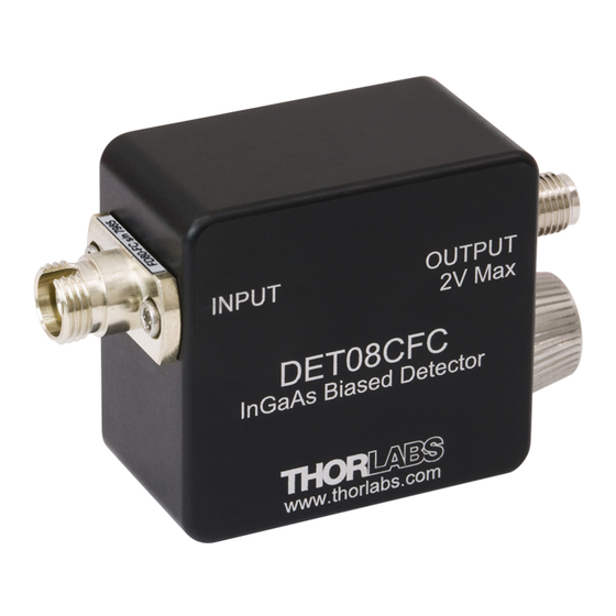
- Page 1 DET08CFC(/M) Fiber Input InGaAs Biased Detector User Guide...
-
Page 2: Table Of Contents
6.2. Typical Response ............13 6.3. Mechanical Drawing ............ 14 Chapter 7 Troubleshooting ............. 15 Chapter 8 Certificate of Conformance ........... 16 Chapter 9 Regulatory ............... 17 Chapter 10 Thorlabs Worldwide Contacts........18 Page 1 Rev B, April 29, 2015... -
Page 3: Chapter 1 Warning Symbol Definitions
DET08CFC(/M) Chapter 1: Warning Symbol Definitions Chapter 1 Warning Symbol Definitions Below is a list of warning symbols you may encounter in this manual or on your device. Symbol Description Direct Current Alternating Current Both Direct and Alternating Current Earth Ground Terminal... -
Page 4: Chapter 2 Description
DET08CFC(/M) Chapter 2 Description The DET08CFC(/M) is a ready-to-use, high-speed InGaAs photodetector for use with FC/PC connectorized fiber optic cables in NIR optical systems. The unit comes with an FC/PC bulkhead connector, detector, and 12 V bias battery enclosed in a compact aluminum housing. The FC/PC connector provides easy coupling to fiber-based light sources. -
Page 5: Chapter 3 Setup
Step 1 in the setup instructions below outline how to mount the detector onto a post. Unpack the optical head, install a Thorlabs TR-series ∅1/2″ post into one of the #8-32 (M4 on the /M version) tapped holes, located on the bottom and side of the housing, and mount into a PH-series post holder. -
Page 6: Chapter 4 Operation
Depicted in Figure 1 is a junction photodiode model with basic discrete components to help visualize the main characteristics and gain a better understanding of the operation of Thorlabs' photodiodes. Series... -
Page 7: Photoconductive
DET08CFC(/M) Chapter 4: Operation 4.3.1. Photoconductive In photoconductive mode, a reverse external bias is applied, which is the basis for our DET series detectors. The current measured through the circuit indicates illumination of the device; the measured output current is linearly proportional to the input optical power. -
Page 8: Junction Capacitance
DET08CFC(/M) The table below compares five common types of detector materials. Dark Sensitivity Material Current Speed (nm) Cost Silicon (Si) High 400 – 1000 Germanium (Ge) High 900 – 1600 Gallium Phosphide (GaP) High 150 – 550 Indium Gallium Arsenide (InGaAs) High 800 –... -
Page 9: Terminating Resistance
DET08CFC(/M) Chapter 4: Operation 4.7. Terminating Resistance A load resistance is used to convert the generated photocurrent into a voltage ) for viewing on an oscilloscope: × Depending on the type of photodiode, the load resistance can affect the response speed. For maximum bandwidth, we recommend using a 50 Ω coaxial cable with a 50 Ω... -
Page 10: 4.11. Battery Replacement
DET08CFC(/M) 4.11. Battery Replacement Thorlabs delivers each detector with an A23 12 V battery installed. This battery is readily available at most retail stores, as well as through Thorlabs. The supplied battery will deliver about 40 hours of operation with a 1 mA load, which is roughly equivalent to a continuous 1.5 mW light source at peak wavelength. -
Page 11: Chapter 5 Common Operating Circuits
DET08CFC(/M) Chapter 5: Common Operating Circuits Chapter 5 Common Operating Circuits RC Filter External Protection Diode Photodetector Voltage Resistor V Bias Regulator 1 kΩ On/Off Switch LOAD Capacitor 0.1 µF Battery Figure 2 Basic DET Circuit The DET Series Detectors are designed according the circuit depicted above. - Page 12 DET08CFC(/M) One can also use a photodetector with an amplifier for the purpose of achieving high gain. The user can choose whether to operate in Photovoltaic of Photoconductive modes. There are a few benefits of choosing this active circuit: •...
-
Page 13: Chapter 6 Specifications
DET08CFC(/M) Chapter 6: Specifications Chapter 6 Specifications All measurements are performed with a 50 Ω load unless stated otherwise. Electrical Specifications Detector InGaAs PIN Active Area Diameter Ø80 um Wavelength Range λ 800 to 1700 nm Peak Wavelength λ 1550 nm Peak Response ℜ( λ... -
Page 14: Response Curve
DET08CFC(/M) 6.1. Response Curve 6.2. Typical Response Figure 4 T = 55 ps, T = 52 ps@ 20/80%, T = 110 ps Page 13 Rev B, April 29, 2015... -
Page 15: Mechanical Drawing
DET08CFC(/M) Chapter 6: Specifications 6.3. Mechanical Drawing 2.23" FC/PC Fiber (56.6 mm) Input Connector 1.50" InGaAs Photodetector (38.1 mm) 1.40" (35.6 mm) 0.95" (24.1 mm) Battery Tube 0.40" (Use Only A23 (10.2 mm) 12 V Batteries) 0.80" 0.40" Mounting Hole (20.3 mm) -
Page 16: Chapter 7 Troubleshooting
DET08CFC(/M) Chapter 7 Troubleshooting Problem Suggested Solutions There is no signal response or Verify that the battery is inserted and has response is slower than sufficient power (>9 V) expected. Verify the proper terminating resistor is installed if using a Voltage measurement device. -
Page 17: Chapter 8 Certificate Of Conformance
DET08CFC(/M) Chapter 8: Certificate of Conformance Chapter 8 Certificate of Conformance TTN020103-D02 Page 16... -
Page 18: Chapter 9 Regulatory
9.1. Waste Treatment is Your Own Responsibility If you do not return an “end of life” unit to Thorlabs, you must hand it to a company specialized in waste recovery. Do not dispose of the unit in a litter bin or at a public waste disposal site. -
Page 19: Chapter 10 Thorlabs Worldwide Contacts
DET08CFC(/M) Chapter 10: Thorlabs Worldwide Contacts Chapter 10 Thorlabs Worldwide Contacts USA, Canada, and South America UK and Ireland Thorlabs, Inc. Thorlabs Ltd. 56 Sparta Avenue 1 Saint Thomas Place, Ely Newton, NJ 07860 Cambridgeshire CB7 4EX Great Britain Tel: 973-300-3000... - Page 20 www.thorlabs.com...
Need help?
Do you have a question about the DET08CFC and is the answer not in the manual?
Questions and answers