
Related Manuals for National Instruments NI Vision PCIe-1433


Summary of Contents for National Instruments NI Vision PCIe-1433
- Page 1 NI Vision NI PCIe-1433 User Manual and Specifications Base, Medium, and Full Configuration Camera Link Frame Grabber NI PCIe-1433 User Manual and Specifications July 2010 374001B-01...
- Page 2 Thailand 662 278 6777, Turkey 90 212 279 3031, United Kingdom 44 (0) 1635 523545 For further support information, refer to the Technical Support and Professional Services appendix. To comment on National Instruments documentation, refer to the National Instruments Web site at and enter ni.com/info the Info Code feedback ©...
- Page 3 Instruments Corporation. National Instruments respects the intellectual property of others, and we ask our users to do the same. NI software is protected by copyright and other intellectual property laws. Where NI software may be used to reproduce software or other materials belonging to others, you may use NI software only to reproduce materials that you may reproduce in accordance with the terms of any applicable license or other legal restriction.
- Page 4 Operation of this hardware in a residential area is likely to cause harmful interference. Users are required to correct the interference at their own expense or cease operation of the hardware. Changes or modifications not expressly approved by National Instruments could void the user’s right to operate the hardware under the local regulatory rules.
- Page 5 Conventions The following conventions are used in this manual: <> Angle brackets that contain numbers separated by an ellipsis represent a range of values associated with a bit or signal name—for example, AO <3..0>. » The » symbol leads you through nested menu items and dialog box options to a final action.
-
Page 6: Table Of Contents
Overview ......................1-2 Power Over Camera Link................1-2 SafePower ..................1-3 Software Overview ......................1-3 NI-IMAQ Driver Software ................1-3 National Instruments Application Software ............1-4 Vision Builder for Automated Inspection.........1-4 Vision Development Module ............1-4 Integration with DAQ and Motion Control .............1-5 Chapter 2 Hardware Overview Functional Overview......................2-1... - Page 7 Contents Appendix A Specifications Appendix B Technical Support and Professional Services Glossary Index NI PCIe-1433 User Manual and Specifications viii ni.com...
-
Page 8: Introduction
I/O Extension Board. For more advanced digital or analog system triggering or digital I/O lines, you can use the NI 1433 and NI-IMAQ with the National Instruments Data Acquisition (DAQ) or Motion Control product lines. Synchronizing several functions to a common trigger or timing event can be a challenge with image acquisition devices. -
Page 9: Camera Link
Chapter 1 Introduction such as data acquisition and motion control devices. The RTSI bus uses the National Instrument RTSI bus interface and ribbon cable to route additional timing and trigger signals between the NI 1433 and up to four National Instruments DAQ, Motion Control, or Vision devices. -
Page 10: Safepower
(non-PoCL) camera or through a conventional cable. Software Overview Programming the NI 1433 requires the NI-IMAQ driver software to control the hardware. National Instruments also offers the following application software packages for analyzing and processing your acquired images. •... -
Page 11: National Instruments Application Software
National Instruments Application Software This section describes the National Instruments application software packages you can use to analyze and process the images you acquire with the NI 1433. -
Page 12: Integration With Daq And Motion Control
Integration with DAQ and Motion Control Platforms that support NI-IMAQ also support NI-DAQ and a variety of National Instruments data acquisition (DAQ) devices. This allows for integration between image acquisition and DAQ devices. Use National Instruments high-performance stepper and servo motion... -
Page 13: Hardware Overview
Configuration Enables Receiver Pixel Clock Serial Control UART Serial Control Data Medium Enables Configuration Receiver Pixel Clock Data Full Configuration Enables Receiver Pixel Clock Figure 2-1. NI 1433 Block Diagram © National Instruments Corporation NI PCIe-1433 User Manual and Specifications... -
Page 14: Camera Link And The Ni 1433
These variable parameters are defined on a per-camera basis in a camera file ( ) supplied by National Instruments. NI-IMAQ camera_model.icd uses the information in this camera file to program the NI 1433 to acquire images from a specific camera. Without this camera file, the driver does not have the information necessary to configure the NI 1433 to recognize the image format of the particular camera you are using. -
Page 15: Hardware Binarization
The following figure illustrates binarization and inverse binarization. NORMAL INVERSE Sampled Data Sampled Data Figure 2-2. Binarization and Inverse Binarization © National Instruments Corporation NI PCIe-1433 User Manual and Specifications... -
Page 16: Multiple-Tap Data Formatter
Chapter 2 Hardware Overview Multiple-Tap Data Formatter Many digital cameras transfer multiple taps, or pixels, of data simultaneously to increase the frame rate of the camera. However, the data in each tap may not be transferred in the traditional top-left to bottom-right direction. -
Page 17: Noise Filtering
The active pixel region selects the starting pixel and number of pixels to be acquired relative to the assertion edge of the horizontal (or line) © National Instruments Corporation NI PCIe-1433 User Manual and Specifications... -
Page 18: Dma Controllers
Chapter 2 Hardware Overview enable signal from the camera. The active line region selects the starting line and number of lines to be acquired relative to the assertion edge of the vertical (or frame) enable signal. • Region of interest—The NI 1433 uses a second level of active pixel and active line regions for selecting a region of interest. -
Page 19: Serial Interface
MAX—Use MAX with a camera file containing preprogrammed commands. When an acquisition is initiated, the commands are sent to the camera. • —Use the National Instruments terminal emulator for clsercon.exe Camera Link, , if a camera file with preprogrammed serial clsercon.exe... - Page 20 Chapter 2 Hardware Overview National Instruments also fully supports the recommended serial API described in the Specifications of the Camera Link Interface Standard for Digital Cameras and Frame Grabbers manual. This manual is available on several Web sites, including the Automated Imaging Association Web site www.machinevisiononline.org...
-
Page 21: Signal Connections
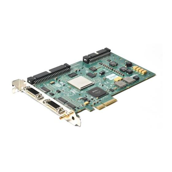
The following figure shows the connectors on the NI 1433 device. 1 Port 0—Base Camera Link Connector 3 SMB Trigger Connector 2 Port 1—Medium/Full Camera Link Connector Figure 3-1. NI 1433 Connectors © National Instruments Corporation NI PCIe-1433 User Manual and Specifications... -
Page 22: Mdr Connectors
Chapter 3 Signal Connections MDR Connectors Port 0 and Port 1 are 26-pin MDR connectors that provide reliable high-frequency transfer rates between the camera and the NI 1433. • For Base configuration cameras, connect one 26-pin MDR Camera Link cable to Port 0 on the NI 1433. •... - Page 23 Full configuration data and enable signals from the camera to the NI 1433. ZCLK± Transmission clock on the Full configuration chip for Camera Link communication between the NI 1433 and the camera. © National Instruments Corporation NI PCIe-1433 User Manual and Specifications...
-
Page 24: Cabling
MDR-26 male plugs linked with a twin-axial shielded cable and are available in two shell configurations. National Instruments recommends that you use the following cables to connect your camera to the 26-pin MDR connectors on the NI 1433: •... - Page 25 Number of external trigger I/O lines..1 Trigger input Voltage range ........0 to 5 V (TTL) Input high voltage ....2.0 V Input low voltage ..... 0.8 V Polarity..........Programmable, active high or active low © National Instruments Corporation NI PCIe-1433 User Manual and Specifications...
- Page 26 Appendix A Specifications Trigger output Voltage range........0 to 5 V (TTL) Output high voltage....3.06 V at 3 mA source Output low voltage ....0.55 V at 3 mA sink Polarity ..........Programmable, active high or active low Maximum pulse rate .......2 MHz Clocks Pixel clock frequency range....20 MHz to 85 MHz The Camera Link specification requires cameras to transmit at a minimum of...
- Page 27 Shock and Vibration Operational shock ........30 g peak, half-sine, 11 ms pulse Tested in accordance with IEC-60068-2-27. Test profile developed in accordance with MIL-PRF-28800F. © National Instruments Corporation NI PCIe-1433 User Manual and Specifications...
- Page 28 Appendix A Specifications Random vibration Operating .........5 to 500 Hz, 0.3 grms Nonoperating ........5 to 500 Hz, 2.4 grms Tested in accordance with IEC-60068-2-64. Nonoperating test profile exceeds the requirements of MIL-PRF-28800F, Class 3. Safety This product meets the requirements of the following standards of safety for electrical equipment for measurement, control, and laboratory use: •...
- Page 29 Instruments WEEE initiatives, and compliance with WEEE Directive 2002/96/EC on Waste and Electronic Equipment, visit ni.com/environment/weee National Instruments (RoHS) National Instruments RoHS ni.com/environment/rohs_china (For information about China RoHS compliance, go to ni.com/environment/rohs_china © National Instruments Corporation NI PCIe-1433 User Manual and Specifications...
- Page 30 Technical Support and Professional Services Visit the following sections of the award-winning National Instruments Web site at for technical support and professional services: ni.com • Support—Technical support at includes the ni.com/support following resources: – Self-Help Technical Resources—For answers and solutions,...
- Page 31 Appendix B Technical Support and Professional Services • Declaration of Conformity (DoC)—A DoC is our claim of compliance with the Council of the European Communities using the manufacturer’s declaration of conformity. This system affords the user protection for electronic compatibility (EMC) and product safety.
- Page 32 Interface standard for digital video data and camera control based on the Channel Link chipset. Channel Link National Semiconductor chipset for high-speed data serialization and deserialization for transmission across cables up to 10 m. © National Instruments Corporation NI PCIe-1433 User Manual and Specifications...
- Page 33 A type of protocol that makes it possible for two devices to synchronize operations. LVDS Low Voltage Differential Signaling (EIA-644). NI-IMAQ Driver software for National Instruments frame grabbers. NI Vision A collection of driver software and utilities that acquire, display, save, and Acquisition Software monitor images from any NI image acquisition device.
- Page 34 A property of an event or system in which data is processed as it is acquired instead of being accumulated and processed at a later time. © National Instruments Corporation NI PCIe-1433 User Manual and Specifications...
- Page 35 RS-422 can be used at distances to 4,000 ft (1,275 m). RTSI bus Real-Time System Integration Bus. The National Instruments timing bus that connects Vision and DAQ devices directly, by means of connectors on the devices, for precise synchronization of functions.
- Page 36 PC, that has the functionality of a classic stand-alone instrument. (2) A LabVIEW software module (VI), which consists of a front panel user interface and a block diagram program. © National Instruments Corporation NI PCIe-1433 User Manual and Specifications...
- Page 37 MDR 26-pin connector, 3-2 overview, 1-2 multiple-tap data formatter, 2-4 connectors, 3-1 conventions used in the manual, v National Instruments support and services, Declaration of Conformity (NI resources), B-2 NI 1433 diagnostic tools (NI resources), B-1 acquisition and region of interest, 2-5...
- Page 38 Index software programming choices, 1-4 software integration with DAQ, 1-5 NI resources, B-1 NI Vision Builder for Automated overview, 1-3 Inspection, 1-4 software programming choices, 1-4 NI Vision Development Module, 1-4 integration with DAQ, 1-5 NI-IMAQ driver software, 1-3 NI Vision Builder for Automated start conditions, 2-6 Inspection, 1-4 trigger control and mapping circuitry, 2-4...
Need help?
Do you have a question about the NI Vision PCIe-1433 and is the answer not in the manual?
Questions and answers