Advertisement
Quick Links
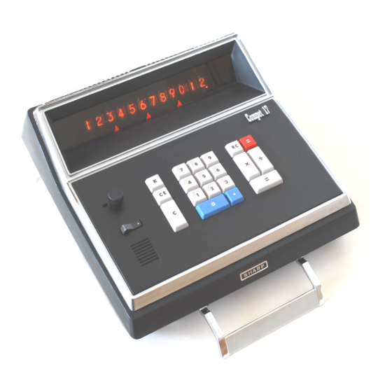
Sharp Compet 17 Calculator
Section: Title and Contents
Page: 1
Rendition: 2020 May 20
Sharp Compet 17
Calculator
Contents
Section
Title & Contents (this page)
Notes, Gate Identification & Signal Names
Block Diagram
Timing
Keyboard & P-Cycle Generator
Control (Major Operation Flags)
Control (F, J & G Flags)
Control (State Matrix)
Control (Outputs)
Registers
Arithmetic
Decimal Point Counters
Display
Power Supply
Timing Diagram
IC Pinouts & Gate Construction
Physical Layout and Connectors
Page
1
2
3
4
5
6
7
8
9
10
11
12
13
14
15
16
17
This schematic has been derived through
reverse engineering.
This is not the manufacter's schematic, nor
is it based on the manufacturer's schematic.
Advertisement

Related Manuals for Sharp Compet 17


Summary of Contents for Sharp Compet 17
- Page 1 Decimal Point Counters Display Power Supply Timing Diagram IC Pinouts & Gate Construction Physical Layout and Connectors Sharp Compet 17 Calculator This schematic has been derived through reverse engineering. Section: Title and Contents This is not the manufacter’s schematic, nor Page: 1 Rendition: 2020 May 20 is it based on the manufacturer’s schematic.
- Page 2 S…, C… The state machine. Multiply or divide operation pending. ♦ This schematic includes the user memory which is not present in the Compet 17 model. Components marked with “§” Divide operation pending. are not present in the Compet 17.
- Page 3 (2nd operand, 48 bits) Decimal Point (PX) Ring Counter M Register (user memory, 48 bits) 12 Nixie Displays Display Latch 1-of-10 Decimal (4 bits) Decoder Point 000987654321. and Drivers Driver Sharp Compet 17 Calculator Section: Block Diagram Page: 3 Rendition: 2020 May 20...
- Page 4 ØnD16 Ø2 ØT ØB2 2SC458 NL21 ØB4 ØnD1 ØnB4 NL15 NL16 NL23 ØB8 ØnD1 ØD1 ØnB8 2SC458 Ø1 ØnD11 ØD11 ØnB8 ØnD16 ØnD12 ØD12 Øn(D16•B8•1) (CPC) Sharp Compet 17 Calculator ØnD13 ØD13 Section: Timing Page: 4 Rendition: 2020 May 20...
- Page 5 Ø3 ØR 2N4401 7-12 NK40 NR40 NR38 KCLR IDLE BUSY 0.001 100K IDLE NORMAL NR35 NK35 MANUAL PMANUAL Øn(D16•B8•1) Ø C Ø2 ØT Sharp Compet 17 Calculator Ø3 ØR Section: Keyboard & P-Cycle Generator Page: 5 Rendition: 2020 May 20...
- Page 6 S2•F•J § 36.4 § S1•nF•J•M d18 § 42.4 § S6•nF•J 45.4 C458 S5•F•J Øn(D16•B8•1) 48.4 S1•F•J 55.4 65.1 S2•nF•J•M 65.2 S2•F•nJ Sharp Compet 17 Calculator 65.3 S2•nF•J•nM 65.4 Section: Control (Major Operation Flags) KCLR Page: 6 Rendition: 2020 May 20...
- Page 7 S2•nF•nJ Ø2 ØT CPA’ Ø3 ØR S1•nJ ØB8 32.4 ØnD16 42.2 S6•nF•J 24.2 38.1 Ø1 Ø C S2•nF•nJ Ø2 ØT Øn(D16•B8•1) Ø3 ØR Sharp Compet 17 Calculator Section: Control (F, J & G Flags) Page: 7 Rendition: 2020 May 20...
- Page 8 F+nJ S1•nF•J•M 7-10 S2•nF•J•M § S1•nF•J•nM 7-11 S2•nF•J•nM § NR11 7-10 S2•nF•J•nM(K) K NK11 2SA549 2SC641 S1•nJ IDLE to P generator NK38 IDLE to keyboard NR38 Sharp Compet 17 Calculator Section: Control (State Matrix) Page: 8 Rendition: 2020 May 20...
- Page 9 S1•nF•J•M KNDP•M•S•nC•nD+KCLR+KMD•S S2•nF•nJ 14.3 45.2 § 54.3 S2•F•J S5•F•J KCE' CMØ 37.2 57.1 § 54.4 S4•F•J S2•F•J CPWØnG 57.2 § 64.2 S2•F•nJ 57.3 57.4 33.2 KEQ•C•D CPYPX Sharp Compet 17 Calculator Section: Control (Outputs) Page: 9 Rendition: 2020 May 20...
- Page 10 ØT Ø2 ØT Ø2 ØT 2SC458 Ø3 ØR Ø3 ØR Ø3 ØR Ø3 ØR Ø3 ØR Ø3 ØR § § § § § § CMØ MØ (CPM) § Sharp Compet 17 Calculator Section: Registers Page: 10 Rendition: 2020 May 20...
- Page 11 ØB2 ØB8 Ø2 ØT C T C Ø3 ØR Carry ØB1 CARRY Ø1 Ø C Latch Ø2 ØT Ø3 ØR ØnD16 Ø1 Ø C Ø2 ØT Ø3 ØR Sharp Compet 17 Calculator Section: Arithmetic Page: 11 Rendition: 2020 May 20...
- Page 12 CPYPX D A1 Q A8 D B1 Q B8 6-10 6-10 Ø C Ø C 2SC458 Ø2 ØT Ø2 ØT ØnB8 Ø3 ØR Ø3 ØR Ø1 Sharp Compet 17 Calculator Section: Decimal Point Counters Page: 12 Rendition: 2020 May 20...
- Page 13 2SC857 V+90D 1S84 110K 2SC857 Hitachi CD81 V+90D 2SC458 110K 2SC857 V+90D 110K 2SC857 V+90D 2SC458 110K Ø3 ØnD1 2SC857 ØnB1+3 2SC458 2SC458 200pF NL35 ØnD1 nPXI ØnB1+3 Sharp Compet 17 Calculator Section: Display Page: 13 Rendition: 2020 May 20...
- Page 14 NL30 192mA NM3 NP2 –24V (VDD) ØnB1+3 white NL31 NK10 NR10 NL32 7-10 2-10 6-10 7-11 2-11 6-11 7-12 2-12 6-12 7-13 7-14 Unused Elements Sharp Compet 17 Calculator § 7-13 Section: Power Supply Page: 14 Rendition: 2020 May 20...
- Page 15 (744 Hz) ØnD1 ØnD2 ØnD16 ØD1416 Øn(D16•B8•1) X and PXI with 000987654321. in the display. ØD n Digit being displayed (LSD) (MSD) One full number cycle in registers Sharp Compet 17 Calculator Section: Timing Diagram Page: 15 Rendition: 2020 May 20...
- Page 16 Controlling pin 6 allows it to function as a sample-and-hold latch, presumably relying on inter-electrode capacitance to hold the state between digit updates (see Display). Sharp Compet 17 Calculator Section: IC Pinouts and Gate Construction Page: 16 Rendition: 2020 May 20 1 ØnD3...
- Page 17 § KMC 31 32 KMR § § KMS 33 34 KMAS § PMANUAL 35 36 lamp * lamp ÷ 37 38 IDLE Sharp Compet 17 Calculator Ø3 39 40 P Section: Physical Layout and Connectors — 41 42 GND Page: 17 Rendition: 2020 May 20 nDPØD 43 44 X...
Need help?
Do you have a question about the Compet 17 and is the answer not in the manual?
Questions and answers