Table of Contents
Advertisement
Advertisement
Table of Contents

Related Manuals for Matrix SATATYA Project Series


Summary of Contents for Matrix SATATYA Project Series
- Page 1 SATATYA Project Bullet IP-Camera The Persistent Vision...
- Page 2 Consignes de sécurité Safety Instructions These instructions are intended to ensure that the user can Ces instructions ont pour but de garantir que l'utilisateur peut Utilisez use the product correctly to avoid danger or property loss. le produit correctement pour éviter tout danger ou perte de propriété. Cautions Précautions •...
-
Page 3: Table Of Contents
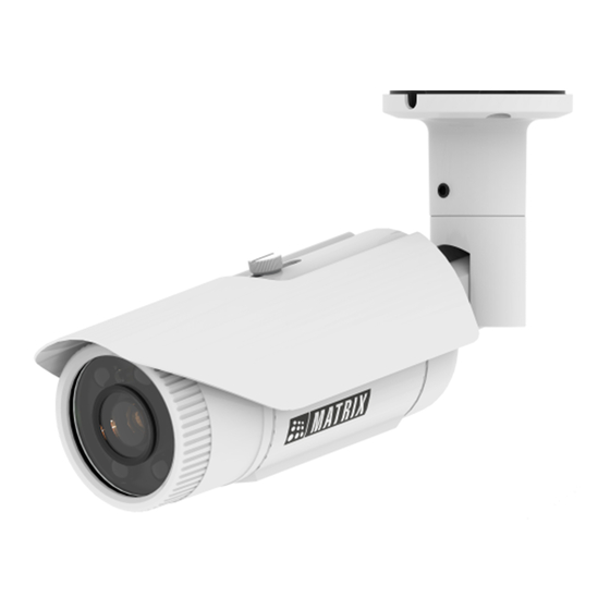
Please read this guide first for correct installation and retain it for future reference. The information 4. Hole for mounting 9. Sunshield in this guide is prevailing at the time of publication. However, Matrix Comsec reserves the right to 5. Pivot Joint 10. Lens make changes in product design and specifications without prior notice. -
Page 4: What Your Package Contains
What your Package contains You can capture near and broader view with lens of 2.8mm and 4.0 mm focal length. For example it can be used in ATM Ÿ Bullet IP Camera Unit and Elevators. Ÿ Wall Mounting Template Ÿ Wall Mounting Screws with Screw Grip (4 nos.) With lens of 6 mm focal length, far and narrow view can be Ÿ... -
Page 5: Installation
Installation Instruction Installation 1. This product is intended to be supplied by a UL listed power Before you start supply unit marked “Class 2” or “LPS” or “PS2” and rated 12VDC, Please make sure, 2A min. Ÿ The device in the package is in good condition and all the assembly parts are included. -
Page 6: Ip66 Protection Accessory Installation
Step 3: IP66 Protection Accessory Installation 1. By default your camera contains the LAN connector fitted by IP66 protection accessory. IP66 accessory LAN Connector Do not remove the “O” ring from its place. Power cable 4. Loosen the tail end of the IP66 accessory by rotating it in anticlockwise direction. -
Page 7: Installing Mounting Template
Step 4: Installing Mounting Template 6. Insert male RJ45 connector into female connector part. Then tighten the middle part by rotating in clockwise direction. • Stick the Mounting Template on the desired Installation surface. • Drill three holes through the markings of the Mounting Template on Wall or Ceiling. -
Page 8: Mounting The Camera
Figure 4 Step 5: Mounting the Camera Base Plate • To avoid cable damage, take the Power, Ethernet, Audio IN, Audio Socket screw OUT, Alarm IN, Alarm OUT cables of the camera through the cable guide on the base plate. see Figure 3 •... -
Page 9: Connecting Cables
Step 7: Connecting Cables • Connect the Ethernet cable to LAN port and Power cable to the Alarm Out 12V DC power supply. Audio IN Alarm IN Audio Out In Premium variants, connect the Audio I/O cables if required. 1. You can connect the Audio Input device such as Mike to the Audio Ethernet input cable of the camera. -
Page 10: Accessing Reset Pin And Sd Card Slot
Accessing Reset Pin and SD card slot 3. Press the Reset switch for minimum 5 sec and release the switch to reset the camera to default settings. If you forget the IP address or login credentials of camera then the camera can be reset to factory default settings using the reset pin. -
Page 11: Adjusting Focus And Zoom In Varifocal Cameras
After Reset or SD card insertion, you may need to set the Adjusting Focus and Zoom in Varifocal Cameras camera focus and camera angle. Figure 10 For greater IR vision during the night mode in 2.8mm focal length bullet cameras, it is recommended to put the sunshield at its minimum position from the camera lens as shown in below figure. -
Page 12: Network Configuration
PC. Then install the software to configure the IP address. In Internet Explorer you can access the camera with Matrix Steps to get the IP address: ActiveX plugin. In other browsers you need to install •... - Page 13 • Enter the User Name and Password. • By default, you can login with User Name as admin, operator or viewer with the password as admin, operator and viewer respectively. • Click on Login. Ÿ The ActiveX control will get installed on your PC. Ÿ...
-
Page 14: Technical Specification
Technical Specification Ÿ Install the Camera software by clicking on Install. Premium Specification Standard Power Supply Adapter 12V DC (802.3af, Class 3) 12VDC 0.7A; max: 8.5W Power Consumption PoE (36V to 57V)(0.3A to 0.2A); max: 10W Connectors Ethernet • The home page of the camera will open and the live view will be displayed. - Page 15 Detection, Object Counting Missing/Suspicious Object ONVIF Profile Environmental Operating Temp. -20 C to +60 C Humidity 5 to 95% RH Missing Object, Suspicious Object, Object Counting and Loitering Detection events will work only in CIBR50MVL12CWP variants of Matrix IP Camera.
- Page 16 MATRIX COMSEC Head Office 394-GIDC, Makarpura, Vadodara - 390010, India Ph: (+91)1800-258-7747 Email: Support@MatrixComSec.com www.matrixvideosurveillance.com...
Need help?
Do you have a question about the SATATYA Project Series and is the answer not in the manual?
Questions and answers