
Related Manuals for KROHNE ALTOSONIC V12


Summary of Contents for KROHNE ALTOSONIC V12
- Page 1 ALTOSONIC V12 / OPTISONIC V6 Operation and Installation Manual Operation & Installation Manual V12-V6 2010-05-31.doc 31/05/2010 1/60...
-
Page 2: Disclaimer (Liability)
Disclaimer (liability) KROHNE is not liable for any damage of any kind by use of the product described in this manual, including, but not limited to direct, indirect, incidental, punitive and consequential damages. This disclaimer does not apply in case KROHNE has acted on purpose or with gross negligence. -
Page 3: Table Of Contents
Swirl compensation..................9 2.1.3. Multipath ultrasonic flow meters ..............10 General description....................11 Detailed description ....................12 2.3.1. Ultrasonic transducer ..................12 2.3.2. ALTOSONIC V12 Meter body ...............13 2.3.3. ALTOSONIC V12 signal converter ..............14 2.3.4. Signal converter enclosure ................14 2.3.5. Main Board Assembly ...................16 Software........................16 2.4.1. - Page 4 Exchange of Electronics Unit ................51 Battery maintenance .....................53 Spare Parts Availability ..................54 Service Availability ....................54 Returning a Device to the Manufacturer ..............54 8.8.1. General Information..................54 Disposal ........................54 8.10 KROHNE Care™....................55 Technical specifications....................56 Marks and Seals .......................57 Operation & Installation Manual V12-V6 2010-05-31.doc 31/05/2010 4/60...
-
Page 5: General Instructions
General instructions. 1.1 Intended use. The ALTOSONIC V12 is a gas flow meter designed for custody transfer applications. Generally speaking, the meter operates within the relevant accuracy limits for all kinds of gases, although there may be some exceptions. A major field of application is measuring natural gas, the meter is suitable to operate at least under the following conditions: * relative density from 0.55 and upwards... -
Page 6: Information Concerning The Documentation
If this document is not in your native language or if you have any problems understanding the text, we advise you to contact your local KROHNE office for assistance. KROHNE cannot accept responsibility for any damage or injury caused by misunderstanding of the information in this document. -
Page 7: Safety Instructions
When the meter is operated or being installed in a potentially explosive atmosphere, consult the manual with instructions regarding explosion safety that is distributed separately. In case you have not received this document, please contact your local KROHNE office in order to get a copy of this document. -
Page 8: Instrument Description
The trajectory of the sound wave is called the acoustic path. A chord is the direct path crossing the pipe from one side to the opposite side. Using reflection, an acoustic path can consist of two or more chords. The name ALTOSONIC V12 is related to its design where 12 chords build 6 acoustic paths. -
Page 9: Swirl Compensation
This component increases or decreases the speed of the sound wave as it moves from one transducer to the other transducer. The transit time from Trd A to Trd B (t ) is: ϕ ⋅ In opposite direction (from Trd B to Trd A) the transit time (t ) becomes: ϕ... -
Page 10: Multipath Ultrasonic Flow Meters
When looking at specific spots in the pipe, the local gas velocity vector may not be exactly parallel to the pipe axis. This effect can be the result of a flow velocity pattern called swirl. This is a frequently occurring velocity pattern where the gas mass in the pipe rotates as it flows. -
Page 11: General Description
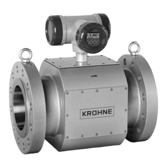
Normally these values are very close to each other. 2.2 General description. The ALTOSONIC V12 meters consist of a meter body with an electronic unit installed on top of it (Figure 2-6). A number of ultrasonic transducers is installed inside the meter body. For... -
Page 12: Detailed Description
Figure 2-6: Location of sensors and electronics of an ALTOSONIC V12 The transducers are electrically connected to the electronic unit on top of the meter by means of coaxial cables. The cabling is protected against mechanical damage and moisture by means of covers or a case that is welded around part of the meter body. -
Page 13: Altosonic V12 Meter Body
-40 C up to +50 C (+70 C pending, type G5) and -40 C up to +100 C (type G6) 2.3.2. ALTOSONIC V12 Meter body The meter body of the ALTOSONIC V12 can be designed and manufactured according to either one of two different concepts, depending of the nominal diameter. -
Page 14: Altosonic V12 Signal Converter
Figure 2-8: Small meter body 2.3.3. ALTOSONIC V12 signal converter The ALTOSONIC V12 ultrasonic gas flow meter has a microprocessor based signal converter. This processor controls the basic flow metering process, performs all the calculations and stores a large amount of data. It offers serial ports (two RS 485 ports) to communicate with other equipment, and programmable digital outputs (pulse/frequency output and status outputs). - Page 15 The lay out of the signal converter enclosure is as shown in the Figure 2-10 (seen from above): screw terminal screw terminal screw terminal screw terminal screw terminal screw terminal block block block block block block back panel back panel back panel back panel flat cable interconnection...
-
Page 16: Main Board Assembly
2.4 Software. 2.4.1. Configuration file. The ALTOSONIC V12 contains a powerful microprocessor that controls the functions and calculations it performs. The microprocessor executes program code consisting of several modules, according to the functions it has to perform. By means of an extensive set of parameters the software can be configured to various sizes and models of flow meters and according to specific requirements depending of applications or customers. -
Page 17: Start Up
The following roles have been defined, hereunder listed in according to the rank in the hierarchy. Developer: restricted to KROHNE R&D employees. Factory : restricted to KROHNE factory employees, to implement factory settings in the meter Service : restricted to authorized service personnel, to the discretion of KROHNE Calibrator :... -
Page 18: The Flow Calculation Module
transducer (transmit pulse) and digitizing and storing the signal on the receiving transducer (receiving pulse). Before starting the digitizing process a “receiving” window must open. The time to open and to close this window (relative to the firing time of the transmit pulse) are dependant of the size of the meter and are set as a parameters in the configuration file. -
Page 19: The Signal Output Module
• number of rejected measurements, • signal strength, • signal to noise ratio. • error indications (if there is a reason for) The flow calculation module prepares data to be used by other modules as: • the signal output module •... - Page 20 PWM output 100% reference : defines the upper limit of the normal range of the numerical value to be converted to a pulse width modulated signal PWM output over range : defines the maximum value of the numerical value to be converted to a pulse width modulated signal.
-
Page 21: Path Substitution
2.4.6. Path substitution The ALTOSONIC V12 is designed for custody transfer applications. In order to maintain the accuracy required for custody transfer measurement under all circumstances, a minimum of three out of five measuring paths must be operational. In case one or two of the five measuring paths fail during operation, an automatic path substitution procedure is started. -
Page 22: Before Installation
Check the packing list to see if you have received all the parts ordered. The ALTOSONIC V12 will arrive in a wooden crate. Carefully unpack the UFM: remove the crate’s lid, unscrew the protecting beams or release the strap belts. Lift the UFM from the crate’s floor using the lifting lugs or eye bolts. -
Page 23: Environmental Requirements
• Humidity: < 95 % RH (closed and heated storage area) • Storage temperature: -40…+65° C / -40…+149° F • Avoid direct solar radiation during long storage periods, store under a sunshade For carbon steel meters or other materials that could suffer from corrosion , a specific point of attention is the conservation of the inner pipe wall. -
Page 24: Installation Requirements
Consult KROHNE for advice in case a PVC with high pressure cut will be operated in the vicinity of the ultrasonic flow meter. -
Page 25: Installation Of The Ultrasonic Gas Flow Meter
Installation of the ultrasonic gas flow meter gas flow straightener 10D or 5D with flow 1.5…3D Figure 4-1: General installation requirements • Always lift the flow meter and its adjacent pipe spools (if applicable) at the lifting lugs or use hoisting straps. •... -
Page 26: Electrical Installation
5.3.1. Power connection NOTE! The ALTOSONIC V12 Ultrasonic Gas Flow Meter needs to be powered from a 24V dc supply. Maximum power consumption is 10 W, a voltage variation of ±10% is acceptable . Operation & Installation Manual V12-V6 2010-05-31.doc... -
Page 27: Digital I/O Connections
The electronic system has a built in diode for protection against connecting the DC power with the wrong (reversed) polarity. Also a fuse is present to protect the electronics against high current. The fuse used is: 800mAT, IEC 60127-2, 250 VAC, 300 VDC, Träge T UL:115V-300VDC IMPORTANT! Always use a fuse with the same specification as mentioned above Figure 5-1: Power connection... -
Page 28: Pulse/Frequency Output
• The power supply to the I/O card should be a NEC class 2 power supply (max 100VA, 24 VDC, IEC 61010-1, Clause 6.3.1 & 6.3.2) • The Protective Conductor terminal of the I/O compartment can be used for cable shielding. -
Page 29: Serial Data Communication (Rs485)
• B/B-: Frequency output inverted related to the line flow whereby this frequency output will stop operating if data valid alarm on status bit C/C- will occur. To do so the frequency output B/B- should be placed in series with status bit C/C- as presented in Figure 5-3 Alarm Alarm... -
Page 30: Serial Communication (Usb)
Krohne. The initial parameter set-up is programmed into the flow meter by means of this serial connection. Entering or overwriting parameters with incorrect values will cause serious problems regarding the functioning of the flow meter. -
Page 31: Ground Connection
IMPORTANT! The temperature rating of the cables used should be higher than 65 5.5 Ground connection The foot of the enclosure has two screw connection points (one M5 thread and one M4 thread) to attach a ground conductor. See the picture below. Figure 5-5: Ground connection This ground connection can be used to connect the upstream and downstream piping to the Ultrasonic Flow Meter (Equipotential). -
Page 32: Operation Of The Ultrasonic Gas Flow Meter
Operation of the ultrasonic gas flow meter. 5.6 Start up The flow meter will be delivered with fully programmed electronics. Additional start up procedures are not necessary. After powering up the flow meter the KRONE logo should be visible on the display of the converter and in about 25 seconds the measurement data will appear. -
Page 33: Available Display Information
Page S1 Status/alarm messages • Page T1 Test page, the display will cycle through the following screens: • KROHNE logo normal • KROHNE logo inverted • Software version 5.9 Operating the display In the normal operating mode an information page can be selected by means of the optical sensitive buttons “up”... - Page 34 Use the > button to enter a submenu Use the < button to go one step back in the menu structure, Press > to open a menu item in order to change its value, the display will show 3 lines •...
-
Page 35: Software Service Tool
6.1 Introduction The ALTOSONIC V12/V6 Monitoring, Configuration and Service Tool (MCST) is a software package developed to support the application of the ALTOSONIC V12 / OPTISONIC V6 ultrasonic gas flow meters. It is designed to be used with a PC or laptop computer with a Windows operating system. - Page 36 This will open a dialog box asking to select or confirm the communication method you intend to use. Figure 6-3: Communication protocol For in filed application MODBUS/RS485 should be the option to choose Press “OK” to confirm A dialog box will appear asking for your user name and password. Figure 6-4: User/Password Type your user name and password and click “OK”.
-
Page 37: User Views
6.2.2. User views Normally after having connected to the meter, using the service tool, the User views will automatically pop up. Figure 6-5: User View The user view has different tabs with specific information. Figure 6-6: User View Tabs If the user view do not appear go to: View >... -
Page 38: Loading Monitoring Configuration
If still the user views are not shown or shown incompletely as presented in this manual than the monitoring configuration is not properly loaded and a monitoring configuration should be loaded manually prior to selecting the User Views 6.2.3. loading monitoring configuration To load a monitoring configuration: Click the button “File”... -
Page 39: Start Up User Views Automatically
Figure 6-10: Browser configuration monitoring Select a “default” monitoring configuration file and press “Open” A dialog box will appear, asking whether you want to start the monitoring function now. Figure 6-11: Start monitoring? Press “Yes” to start the monitoring function. To activate the user views go to: View >... -
Page 40: Viewing Data Unformatted
Click “Settings”. A window “Settings” with 4 tabbed sheets will open. Figure 6-13: Settings menu On the sheet “”Auto start” check the box “Start monitoring after connecting” and click the button “Use current configuration”, or Click “Browse” and choose default.mom Click “OK”... -
Page 41: Creating Reports
The data that will be presented is the data as currently being collected from the meter: only the values of the variables as defined in the monitoring configuration file. Figure 6-15: Unformatted data 6.2.6. Creating Reports. The service tool has been developed to also enable you to create records regarding the state of the ultrasonic flow meter and the way the meter performs. -
Page 42: Reporting Related To Calibration Parameter Settings
6.2.6.1. Reporting related to calibration parameter settings. Click “Parameters” to open a window in which all parameters are listed. Figure 6-17: Parameter list Use the scroll bar at the right side of the window to scroll trough the list and the scroll bar at the bottom to display the columns you are interested in. - Page 43 Select “Calibration Parameter Report” A printable preview of the Calibration Parameter Report will be displayed Figure 6-19: Preview calibration report The small panel at the left side lists – as a tree structure - all the items included in the report. You can click the highlighted “tree”...
-
Page 44: Create A File Listing The Parameters In Csv Format
have the Crystal Reports software installed on your computer you will not be able to read the document afterwards. 6.2.6.2. Create a file listing the parameters in CSV format: Click “Tools” to open the Tools menu Click “Reporting” to open the Reporting submenu Click “Parameters”... -
Page 45: Reporting Related To Process Values
In order to store the parameter list in .XML format: Click “Tools” to open the Tools menu Click “Reporting” to open the Reporting submenu Click “Parameters” to open a window in which all parameters are listed. Click “Reports and Exports” Click “Export to XML…”... -
Page 46: Adjusting Meter Factor (For Authorised Personnel Only)
To restart the logging process: Open the “Monitoring” menu Click “Logging” The check mark will reappear and the status field will display “Log.On” and turn to green again. Logged data will be stored in a file for each day (provided it is the same meter). The software will automatically assign a name to file where the logged data will be stored, the date will be part of the file name (see also Figure 6-13) When the logging process is restarted - after it has been interrupted –... - Page 47 Figure 6-25: Choosing meter factor (object tree) The right side of the screen shows the following information: Figure 6-26: Applying new meterfactor The meter factor can be filled into the field, named “Value”. Also change MeterConst_Rev! when uni directional calibration is used Operation &...
- Page 48 Next steps are: Click “Apply” Click “Commit” Click “Save” Response: “Writing data to flash disk” Save Configuration file by clicking on File > Save Flow meter Configuration as XML file… Figure 6-27: Save configuration file Operation & Installation Manual V12-V6 2010-05-31.doc 31/05/2010 48/60...
-
Page 49: Maintenance
Maintenance 7.1 Periodic maintenance The ALTOSONIC V12 has no moving parts that can wear and tear. No service or maintenance is required, unless the meter gets corroded or heavily contaminated. It is however good practice to make a log file (see par. 6.3) on regular basis. It is not to be... -
Page 50: Exchange Of Transducers - Pressurised Condition
Transducers can be replaced under pressure, just in case it does happen (MTTR < 15 min.). KROHNE supplies a transducer retraction tool as an option (contact KROHNE for details). The instructions for transducer exchange with this device are found in a specific user manual. -
Page 51: Exchange Of Electronics Unit
Figure 7-2: Transducer extraction tool in retracted position 7.4 Exchange of Electronics Unit WARNING! Do not open the electronic housing if the electronics is powered in an hazardous environment. Pending on local safety regulations, remove the power or use gas detection equipment. - Page 52 Figure 7-3: Unscrew cover and pull out display unit Unscrew the two M4 screws (3) at the electronics assembly (4). Pull the carrier frame with the electronic boards out of the enclosure. Be carefull to disconnect cables and wiring as required to allow to take the carrier frame out of the enclosure.
-
Page 53: Battery Maintenance
Figure 7-5: Insert new board and finish exchange Remove the holding plate from the front side of the carrier frame. Use a screw driver and insert it as indicated on the device itself to release the part. Remove flat cables that interconnect printed circuit boards on the front side and the flat cable that connects to the display module Disassemble printed circuit boards out of the assembly (4). -
Page 54: Spare Parts Availability
7.6 Spare Parts Availability It is the policy of KROHNE to provide operational spare parts for any flow meter or major accessory for a period of ten (10) years after shipment of the final production run of that flow meter model. -
Page 55: Krohne Care
Sensitive fiscal data is left out of this maintenance audit trail to avoid any violence of clients’ fiscal data confidentiality. KROHNE stores the maintenance data in an on-line database and offers assistance to inform clients about the performance of their metering equipment on a 24-hour basis. -
Page 56: Technical Specifications
Technical specifications Flow Velocity Range flow rate flow rate minimum maximum [m³/h] [m³/h] 4 " 6 " 1800 8 " 3100 10 " 4800 12 " 6600 14 " 8000 16 " 10100 18 " 12500 20 " 14800 24 " 20600 Diameter Range 100 / 4”, 150 / 6”, 200 / 8”, 250 / 10”, 300 / 12”, 350 / 14”, 400 /... -
Page 57: Marks And Seals
Marks and Seals The electronics and acoustic transducers can be exchanged freely, without the need for re calibration. Nevertheless the electronic board will be sealed to secure the parameter settings of the electronics. Remove the cover Remove display Remove plastic support Locate the protective switch and place seal ON = free... - Page 58 Optional it can be decided to seal also the cover of the electronic housing as can seen below Figure 9-2: External sealing (optional) Secondly the tag plate needs to be sealed: Example of tag plate (true user tag plate may differ from example below): Figure 9-3: Tag plate informatio (example) Location of the tag plate on UFM Operation &...
- Page 59 Figure 9-4: Location of tag plate Sealing of tag plate is done by two sealing screws and sealing wire as can be seen in figure below or the tag plate can be mounted by welding or rivets, so that removal without destroying the tag plate is not possible.
- Page 60 Figure 2-4: Swirl Compensation ...................10 Figure 2-5: Path configuration and pipe cross section with multiple acoustic paths....11 Figure 2-6: Location of sensors and electronics of an ALTOSONIC V12 ......12 Figure 2-7: sensor & connector assembly................13 Figure 2-8: Small meter body ....................14 Figure 2-9: Converter housing ....................14...
Need help?
Do you have a question about the ALTOSONIC V12 and is the answer not in the manual?
Questions and answers