Table of Contents
Advertisement
Quick Links
Advertisement
Table of Contents

Subscribe to Our Youtube Channel
Related Manuals for Progeny C4


Summary of Contents for Progeny C4
- Page 1 Compact Controller Manual...
-
Page 2: Table Of Contents
Table of Contents INTRODUCTION _______________________________________ 3 COMPATIBLE EQUIPMENT & CREDENTIALS ______________ 3 C4 ANATOMY_________________________________________ 4 EXAMPLE CONFIGURATIONS ___________________________ 5 CONNECTION DIAGRAM _______________________________ 9 QUICK START GUIDE _________________________________ 10 OTHER QUICK STARTS _______________________________ 10 QUICK PROGRAMMING TIPS __________________________ 10 INDICATIONS ________________________________________ 11... -
Page 3: Introduction
Introduction The C4 is the latest compact controller from Progeny. C4 can work alone as a combined controller Keypad or Controller RFID reader or both. C4 can also be used with an externally connected Keypad, Reader or Reader-Keypad. The latter allows the role of the C4 to become a programming station or touch sensitive Request to Exit button or both. -
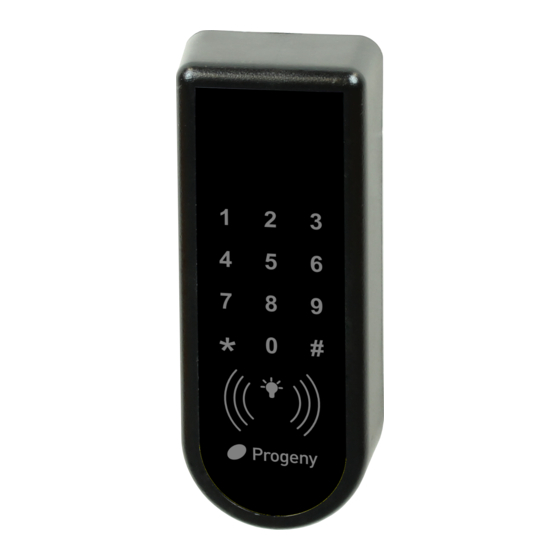
Page 4: C4 Anatomy
C4 Anatomy Anatomy of the C4 Controller / Keypad / Reader / Request to Exit Button Figure 1 Document # MAN0001 Issue 4.29 Page 4 of 34... -
Page 5: Example Configurations
Example Configurations C4 Only This is the simplest of the configurations with the C4 mounted on the outside of the access door. A locking device and a power supply are all that need to be added to complete the system. - Page 6 C4 as Controller with External RFID Reader In this configuration, the C4 controller is moved to the secure side of the access door. From this position, it can be used for programming as before but also the RFID reader can also be used to provide Credential IN / Credential OUT functionality.
- Page 7 C4 as Controller with External Keypad & RFID Reader In this configuration, the C4 controller is also moved to the secure side of the access door. In this position, it can be used for programming as before but also the RFID reader can be used to provide Credential In / Out functionality.
- Page 8 If the locking device is a magnet then a Green Call point is going to be required for emergency egress. The keypad on the C4 is used for programming. The access code can be from 1 to 8 digits in length. This configuration can be used for: •...
-
Page 9: Connection Diagram
Connection Diagram Figure 2 Document # MAN0001 Issue 4.29 Page 9 of 34... -
Page 10: Quick Start Guide
Quick Start Guide To quickly set up and test your controller follow this procedure. Wiring Connect the locking device to the controller. Note if you are connecting to a magnet or any other fail open device you will need to set the “Lock Drive Mode”... -
Page 11: Indications
Indications Indicators Colour visual status indication can be found on the rear edge of the controller and repeated at the Keypad or Credential readers if these are connected. These indicators have the following meanings. Keypad Status LED Meaning Blue Normal Standby Green Lock released Flashing... -
Page 12: Programming
Programming The C4 controller is capable of being programmed “Stand-Alone” from the onboard or externally connected Keypad. If planning to use the external keypad then you may need to enable the Star Key from the integral keypad (See engineers function 19). -
Page 13: User Menu
User Menu The User Menu is accessed by entering * followed by the User Password. The default for this is 654321. User Menu # Description Default Value * 00 User Menu Password 6 5 4 3 2 1 * 01 Access Code None * 04... -
Page 14: Access Code
Access Code Setting the Access Code User Function 01 The C4 controller has a single access code that can be programmed. The access code can be any number of digits from 1 to 8. This example would set a 4 digit Access Code “1234”. -
Page 15: Credentials (Cards & Fobs)
Credentials (Cards & Fobs) Adding Credentials Adding or enabling credentials by entering the Identification Number (ID) can be useful when the credentials themselves are not available or if a large number of credentials need to be added. Single Credential: Note: Some Credentials have a serial number printed on them. - Page 16 Disabling Credentials Single Credential If a Credential is reported lost or stolen, the Credential can be disabled to remove the security risk without affecting any other Credential users. Enter User Password Block of Credentials * 6 5 4 3 2 1 Status LED will Flash The quickest way to disable a whole group of Credentials is to use the...
-
Page 17: Engineer Menu
Program an Administrator Credential User function 10 Enter User Password * 6 5 4 3 2 1 A single Crystal Credential (Card or Status LED will Flash Fob) can be enabled to act as the “User Menu Administrator Credential”. Using a Credential like this will simplify and speed up the management of other Select User Admin Credential * 1 0... - Page 18 Lock Release Time Lock time is the amount of time that the locking device is released following a valid Credential or the triggering of the RQE input. This may be from 0 to 99 seconds. If a door sensor is fitted then the auto relock feature means that the lock time will be cut short once the door closes again.
- Page 19 Penalty Time This feature can slow down persons who are trying to gain access by using successive codes. As soon as an incorrect code is detected at the Keypad this penalty time is invoked, preventing any further access attempts until the timer elapses. Programming the Penalty Time The factory set default penalty time is 0 seconds (Disabled).
- Page 20 Touch to Exit Function The C4 Controller has a Capacitive sensor over the entire flat front surface. When the controller keypad is used in conjunction with an external keypad or reader or both, it can double up as a “Request to exit button” with a large easy to use surface.
- Page 21 Lock Drive Mode The electronic lock drive from a C4 controller switches the negative supply to the lock. By default, the output is programmed to drive a “Fail Secure” locking device. Power is only applied to the lock during the lock release time.
- Page 22 Auto Relock This function is used to control the behaviour of the controller after the door sensor input detects that the door is opened and closed after a valid lock release. If enabled, the door will be automatically locked once the door is closed, effectively shortening the lock release time. Programming Auto Relock Feature This example flow diagram shows the...
- Page 23 98 Clear Access Code Two Factor Authentication The C4 provides both access code and credential identification methods. These can be combined so that both a valid credential and the access code have to be entered to release the lock. Range of Values:...
- Page 24 Controller Alarm Volume The C4 Controller has a speaker that can be used for alarm sound. The volume of that sound can be controlled using this engineers function. The range of Values: 0 = Off 15 = Full Volume Default Value:...
- Page 25 External Reader Alarm Volume Compatible external readers have a speaker that can be used for alarm sound. The volume of that sound can be controlled using this engineers function. The range of Values: 0 = Off 15 = Full Volume Default Value: 15 = Full Volume Related Engineers Menus:...
- Page 26 Controller / Reader Brightness Control The C4 Controller has a status light that can be made brighter or darker as the application demands. Mostly the default value is fine. However, in some unsupervised locations, it may attract the attention of vandals and it may be preferable to turn the brightness down to 0.
- Page 27 Removing the Access Code Engineer’ function 98 will erase the access code. N.B. • The Access Code will not work • Any Credential data will be unaffected • The User and Engineers Passwords are unaffected Reset User Password It can be useful for the engineer to Enter Engineer Password reset the user password.
-
Page 28: Restoring Factory Settings
Engineer Password The passwords are the means by which the commissioning engineer gains access to the programming functions. This is a 6-digit number and can be changed by using the following procedure. Changing the Engineer Password Default *123456 Restoring Factory Settings Reset Sequence The reset button allows the engineer to perform a factory reset. -
Page 29: Installation
3. Pass the cable through the light pipe back plate & make all connections to 4. Screw the C4 Controller Into place over the light pipe. 5. Test operation of the system before applying the membrane label. - Page 30 A more detailed explanation of Back E.M.F. can be located at our website here: https://progeny.co.uk/back-emf-suppression Lock Cable Volt Drop Figure 3 shows how the voltage at the locking device varies with cable length and core size.
- Page 31 Lock Voltage v Cable Distance Supply = 13.5V Lock = 12V 0.5 Amp Cable Distance (metres) 7/0.2 16/0.2 24/0.2 32/0.2 Figure 3 Document # MAN0001 Issue 4.29 Page 31 of 34...
-
Page 32: Inputs
Inputs Request to Exit (RQE) The RQE “Request to Exit” input is used to trigger the lock release timer. The input accepts a normally open voltage free contact. Generally, this input is used to provide egress where the locking device does not provide a mechanical override. -
Page 33: Specification
External Reader / Keypad Only one reader may be connected to the external reader input. Cable & Connections: Always use screened, none twisted cable. Don’t exceed the 100m cable limitation. Door Alarm The door failed to close alarm is indicated on the Controller Keypad and (if connected) the External Reader. - Page 34 No liability is accepted for loss damage or injury as a consequence of using these products or instructions. Document Number: MAN0001 Firmware Version Number: V4.20 WEEE Certificate: WEE/MM5806AA Copyright Progeny Ltd 2017, all rights reserved. Document # MAN0001 Issue 4.29 Page 34 of 34...
Need help?
Do you have a question about the C4 and is the answer not in the manual?
Questions and answers