
Related Manuals for Munters GreenNet


Summary of Contents for Munters GreenNet
- Page 1 GreenNet/ Comm-Box Installation and User Manual Green Net & Comm-Box Controller Software Ag/MIS/UmEN-2740-05/19 Rev 1.3 P/N: 116793...
- Page 2 Munters reserves the right to effect modifications to the apparatus in accordance with technical and legal developments. © Munters AB, 2019...
-
Page 3: Table Of Contents
4.1.3 Technical Support ..........................4.2 SIM Card and Modem Definition -------------------------------------------------------------------------------------------------------------------------- NETWORK SETUP ------------------------------------------------------------------------------------------------------------------------------------- 21 PC SOFTWARE CONFIGURATION----------------------------------------------------------------------------------------------------- 23 6.1 Tools ---------------------------------------------------------------------------------------------------------------------------------------------------------------------------------------- 6.1.1 Language .............................. 6.1.2 Setup Menus ............................6.1.3 Network Setup ............................ 6.1.4 Siren Activation ........................... © Munters AB, 2019... - Page 4 ................. 6.2.3.1 Creating a New Category ................6.2.3.2 Creating a New Graph ..................6.2.3.3 Editing a Graph ............... 6.2.3.4 Sensor Settings in GreenNet ................6.2.3.5 Changing the Time Frame ................. 6.2.3.6 Saving the Template ..................6.2.3.7 Exporting to Excel ..............
-
Page 5: Introduction
The information contained herein has been prepared by qualified experts within Munters. While we believe the information is accurate and complete, we make no warranty or representation for any particular purposes. The information is offered in good faith and with the understanding that any use of the units or accessories in breach of the directions and warnings in this document is at the sole discretion and risk of the user. -
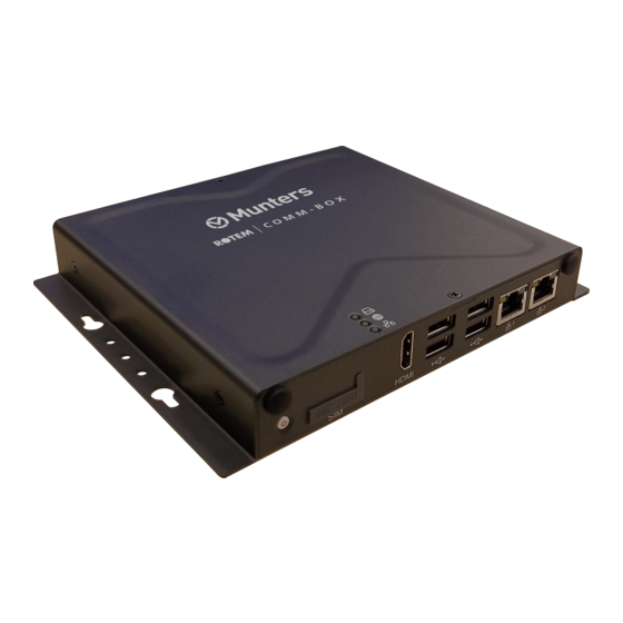
Page 6: Comm-Box
2 Comm-Box Comm-Box provides complete access to your Munters controllers, including monitoring and control capabilities, from any computer. 2.1 Junction Box Connecting a Comm-Box directly to a controller requires a Junction Box. Refer to Connecting the Comm- Box to a Controller, page 8. -
Page 7: Comm-Box Hardware Installation
3 Comm-Box Hardware Installation This document details how to install Munters' Comm-Box unit. Installation consists of: Mounting the Comm-Box • Grounding • Connecting the Comm-Box to the Internet • Connecting the Comm-Box to a Peripheral Device • Connecting the Comm-Box to a Controller •... -
Page 8: Connecting The Comm-Box To The Internet
(instead of to a communication unit). In this situation the Comm-Box must be wired to the controller communication card. Disconnect the power before beginning! WARNING! Only an authorized electrical technician may perform this procedure! WARNING! Controller to Junction Box Wiring • Comm-Box to Junction Box Wiring • © Munters AB, 2019... -
Page 9: Controller To Junction Box Wiring
4. Connect the cable shield wire to the controller ground strip. Figure 1: RS-485 Wiring The Comm-Box comes with the power supply wired to the unit. See Figure 2. • Figure 2: Comm-Box power supply wiring © Munters AB, 2019... - Page 10 1 Insert the Junction Box 9-Pin Connector into COM1 (see Figure 3). Figure 3: Insert 9 Pin Connector 2. Insert the two wires coming from the Junction Box cable into the ports (see Figure 4 and Figure 5). Figure 4: Junction Box Wiring to Comm-Box © Munters AB, 2019...
- Page 11 (#3) in the port as shown in Figure 4. Place both black cables into the ports as shown in Figure 4; either cable can be placed in either port. Figure 5: Power Supply – Comm-Box – Junction Box Setup © Munters AB, 2019...
-
Page 12: Comm-Box Communication
GreenNet • TeamViewer • There are two ways to enable the Comm-Box to communicate to controllers (via the GreenNet software): TeamViewer via an existing LAN • TeamViever via a modem and a data SIM card • 4.1 TeamViewer Definition... - Page 13 The Remote Control ID and Password can be used on other computers to remotely access the Comm-Box. 2. Enter your Partner ID (found on the silver sticker on the Comm-Box carton): The following screen appears: 3. Enter the password: $Rfgt5. The following screen appears: © Munters AB, 2019...
-
Page 14: Setting Up Teamviewer: Retrieved Id
This is the Green Net program as viewed through TeamViewer. 4. To simplify moving through screens, Munters recommends clicking on the Actions tab and checking the Send key combinations checkbox. 4.1.2 S ETTING UP IEWER ETRIEVED In the event that the Silver Sticker ID does not work, the following procedure explains how to find the Comm-Box’... - Page 15 Figure 7: Comm-Box set up The following screen appears: Figure 8: Controller Definitions 2. In this screen: o In Controller Startup > Network Setup Controller Startup select a controller type (Green Field or Green Climate). © Munters AB, 2019...
- Page 16 Click OK. The following screen appears: Figure 9: Controller Scan 3. When the screen appears, click “r” five times (rrrrr). There is no need to wait until the scan finishes. The following screen appears. Figure 10: Sign in screen © Munters AB, 2019...
-
Page 17: Technical Support
1. On the keyboard connected directly to the Comm-Box, press the “R” key five times. The following screen appears: Figure 12: Sign in screen 2. Enter the following in lower case letters: o User name: support o Password: support © Munters AB, 2019... -
Page 18: Sim Card And Modem Definition
1. Place SIM card in a smart phone. Allow the phone to identify the card. 2. Remove the sim card and place it in the Comm-BOX. Figure 14: SIM Card Slot 3. Go to Setup > SMS. © Munters AB, 2019... - Page 19 Select Quectel in the Modem Brand drop down list. o Define the baud rate as 115200. 5. In Setting > Send Info, add a user and phone number. 6. Click Init. The following screen appears. © Munters AB, 2019...
- Page 20 Figure 16: Test Screen © Munters AB, 2019...
-
Page 21: Network Setup
NOTE The network test is an endless loop and only stops by pressing the Stop button. (The loop is on controllers 1-50). Figure 18 displays a drop down list from which the required controller start up is selected. © Munters AB, 2019... - Page 22 Figure 18: Local Communication Setting screenshot – part 2 © Munters AB, 2019...
-
Page 23: Pc Software Configuration
• Set Controller Name • Collect Main Screen • Setting Block Size • Delay Setting • 6.1.1 L ANGUAGE From the dropdown list, select the required language. • Click OK. • Figure 20: Language Selection Box © Munters AB, 2019... -
Page 24: Setup Menus
When the Software does not operate there are no SMS messages. • Select Setup > SMS Alarm Setting. The SMS Alarm Setting window opens. Select which messages to receive. Otherwise, clicking on the Select All button marks all alarms. Figure 22: SMS Alarm Setting Selection © Munters AB, 2019... - Page 25 Figure 23: SMS Alarm Setting NOTE Figure 23 is an example only; the actual screen depends on which controllers are configured in your system. © Munters AB, 2019...
-
Page 26: Sms Setting
Figure 24: Setup Menu List SMS Setting screen is used to define to whom you would like to send SMS messages. Note that there is no connection to the controller's type. Figure 25: SMS Setting Screen © Munters AB, 2019... -
Page 27: Communicating Via Cellular Or Mobile From Your Cellular Phone
Figure 26: Farm Name Entry Box All data will be collected to the Farm Directory when the Local Connection is selected. NOTE GREENNET Farm name must be in English in order for an SMS be delivered properly. © Munters AB, 2019... -
Page 28: Set Controller Name
User defined House name. Use a name that will help you to identify the houses easily and will be used as the directory name for collected Data. NOTE GreenNet Forbidden characters: \ / * ? < > Figure 27: Available House Number Window 6.1.9 C... -
Page 29: Setting Block Size
: Delay Setup – Screenshot 6.2 Quick Access Buttons Main Screen • Graph • Print • Active Alarms • Zone selection for Green Climate • Hot Keys • Collect • History • Load Settings to the Controller • © Munters AB, 2019... -
Page 30: Main Screen
Figure 31: Sample Irrigation Screen 6.2.3 G RAPH Click the Graph button to view controller data in graphs. The following sections detail the Graph function. Creating a New Category • Creating a New Graph • Editing a Graph • © Munters AB, 2019... -
Page 31: Creating A New Category
6.2.3.1 Creating a New Category 1. Click 2. In the text box, type the category name. 3. Click OK. 6.2.3.2 Creating a New Graph 1. Click The Add a New Graph window opens. Figure 32: New Graph Properties Window © Munters AB, 2019... -
Page 32: Editing A Graph
4. Choose background color. 5. The check boxes determine what details appear on the graph. Click the required boxes. 6. Click Save. The graph displays the new settings. 6.2.3.4 Sensor Settings in GreenNet Sensor to Collect • Time Refresh •... -
Page 33: Changing The Time Frame
1. Click The Time Frame fields appear. Figure 34: Select Time Frame Window 2. In the From and To fields, select the required dates. 3. Click Apply. 4. If required, change the default time frame. © Munters AB, 2019... -
Page 34: Saving The Template
To separate the data lines, select 6.2.3.11 File The File menu has the following functions: • Load Offline Data Files: Enables loading offline data files • Application Settings: Enables setting the desired units of measure between the U.S. or Metric system © Munters AB, 2019... -
Page 35: Print
CTIVE LARMS GreenNet displays the active alarms with a short message describing the alarm type. The alarm icon lights up when an alarm is active and it will automatically pop up a screen showing alarm and cause. Any change in alarm will pop up that screen. After it is close it can be reopened by pressing the alarm icon. -
Page 36: Collect
• In addition, there is an automatic data collection to a Microsoft Access - database. When Local connection is selected all the data will be collected to the Farm Directory that was defined in Figure 26. © Munters AB, 2019... -
Page 37: History
Load settings to a controller (Figure 41: Select a controller number and the location of the file to load (In order to enter this menu you must enter a password that can only be received from your local dealer). © Munters AB, 2019... -
Page 38: Save Settings From Controllers
The program creates a different file for each controller. The settings can be transferred to other controllers or serve as backup settings in case of malfunctions. 6.2.12 S Send table settings to selected controllers or to all of the controllers. © Munters AB, 2019... -
Page 39: Switch Between Controller Types
Use the “Switch to …” buttons to switch between available controller types. When connecting to a specific type of controller, for example Green Field all available Green Field units will be visible. NOTE Green Net The icons only appear if they exist on the network. © Munters AB, 2019... -
Page 40: Warranty
Munters plant was required: if this is not done, the user is fully responsible for the damage which they could suffer. - Page 41 The use of non-original spare parts or incorrect assembly exonerates the manufacturer from all liability. Requests for technical assistance and spare parts can be made directly to the nearest Munters office. A full list of contact details can be found on the back page of this manual.
- Page 42 Munters Brasil Industria e Comercio Ltda, Phone +55 41 3317 5050, Canada Munters Corporation Lansing, Phone +1 517 676 7070, China Munters Air Treatment Equipment (Beijing) Co. Ltd, Phone +86 10 80 481 121, Denmark Munters A/S, Phone +45 9862 3311, Munters India, Phone +91 20 3052 2520,...
Need help?
Do you have a question about the GreenNet and is the answer not in the manual?
Questions and answers