Table of Contents
Advertisement
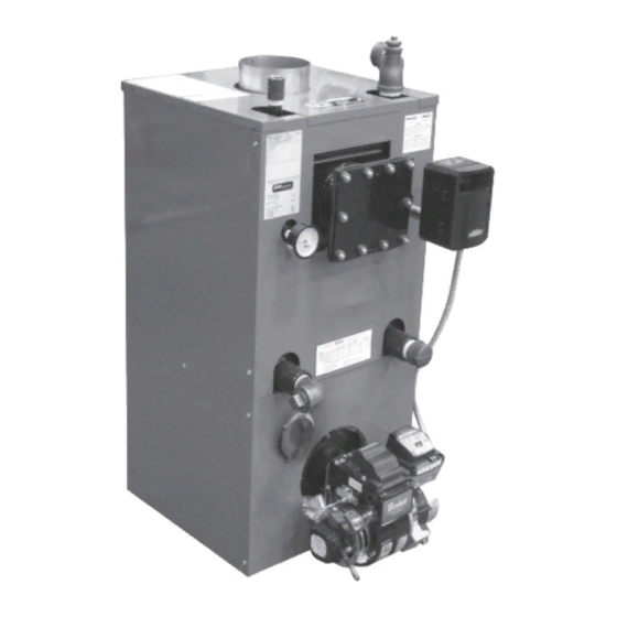
Installation, Operating and Service Instructions for
AP-U
Models:
• AP-110U-N
• AP-110U-T
• AP-154U-N
• AP-154U-T
Manual Contents
1.
General Information . . . . . . . . . . . . . . . . . . . . . .5
2.
Pre-Installation . . . . . . . . . . . . . . . . . . . . . . . . . .7
3.
Water Piping and Trim . . . . . . . . . . . . . . . . . . .10
4.
Venting . . . . . . . . . . . . . . . . . . . . . . . . . . . . . . .15
5.
Electrical . . . . . . . . . . . . . . . . . . . . . . . . . . . . . .17
6.
OIl Piping . . . . . . . . . . . . . . . . . . . . . . . . . . . . .20
7.
System Start-Up . . . . . . . . . . . . . . . . . . . . . . . .22
8.
Operating . . . . . . . . . . . . . . . . . . . . . . . . . . . . .28
9.
Maintenance & Service Instructions . . . . . . .32
10. Boiler Cleaning . . . . . . . . . . . . . . . . . . . . . . . . .34
11. Troubleshooting . . . . . . . . . . . . . . . . . . . . . . . .36
12.
Service Parts . . . . . . . . . . . . . . . . . . . . . . . . . .42
TO THE INSTALLER:
Affix these instructions adjacent to boiler.
TO THE CONSUMER:
Retain these instructions for future reference.
For service or repairs to boiler, call your heating contractor. When seeking information on boiler, provide
Boiler Model Number and Serial Number as shown on Rating Label.
110839-01 - 8/20
TM
Page
• Natural Draft
• Oil-Fired
• Water Boiler
Advertisement
Table of Contents

Related Manuals for New Yorker AP-U AP-110U-N


Summary of Contents for New Yorker AP-U AP-110U-N
-
Page 1: Table Of Contents
Installation, Operating and Service Instructions for AP-U • Natural Draft • Oil-Fired • Water Boiler Models: • AP-110U-N • AP-110U-T • AP-154U-N • AP-154U-T Manual Contents Page General Information ..... .5 Pre-Installation . - Page 2 Installation & Service Manual AP-U IMPORTANT INFORMATION - READ CAREFULLY All boilers must be installed in accordance with National, State and Local Plumb- All boilers must be installed in accordance with National, State and Local Plumb- ing, Heating and Electrical Codes and the regulations of the serving utilities. These ing, Heating and Electrical Codes and the regulations of the serving utilities.
- Page 3 Installation & Service Manual AP-U DANGER DO NOT store or use gasoline or other flammable vapors or liquids in the vicinity of this or any other appliance. WARNING Improper installation, adjustment, alteration, service or maintenance can cause property damage, personal injury or loss of life.
- Page 4 Installation & Service Manual AP-U WARNING This boiler contains very hot water under 12 - 15 PSI pressure. DO NOT unscrew any pipe fittings nor attempt to disconnect any components of this boiler without positively assuring the water is cool and has no pressure. Always wear protective clothing and equipment when installing, starting up or servicing this boiler to prevent scald injuries.
-
Page 5: General Information
Installation & Service Manual AP-U General Information Figure 1-1: AP-U Series Boiler Dimensional Data Table 1-2: Dimensional D (See Figure 1-1) Dimension Water Capacity Approx. Boiler Model Number ‘A’ (gallons) Shipping Weight (lb.) AP-110U-N(T) 34-9/16 10.1 AP-154U-N(T) 41” 15.4 Note: Maximum Working Pressure: Water 30 PSI shipped standard. 110839-01 -8/20... - Page 6 Installation & Service Manual AP-U General Information (continued) Table 1-3: Rating Data Burner Capacity DOE Heating AHRI NET Minimum Chimney Requirements Boiler Model Capacity - Ratings AFUE % - MBH Round In. Rectangle Height Ft. Dia. In. x In. AP-110U-N(T) 0.75 86.2 8 x 8...
-
Page 7: Pre-Installation
Installation & Service Manual AP-U Pre-Installation A. INSPECT SHIPMENT carefully for any signs of be constructed in accordance with NFPA 31. damage. DO NOT install boiler on carpeting. 1. All equipment is carefully manufactured, 3. FOR BASEMENT INSTALLATION, provide a inspected and packed. - Page 8 Installation & Service Manual AP-U Pre-Installation (continued) C. REMOVE CRATE 5. For boiler located in a confined space or an unconfined space in a building of unusually 1. Remove all fasteners at crate skid. tight construction, provide outdoor air with the 2.
- Page 9 Pre-Installation (continued) INSTALLATION INSTRUCTIONS FOR OPTIONAL SHIELD REQUIRED FOR COMBUSTIBLE FLOOR This shield for combustible floors is intended for use only with the following New Yorker oil-fired boilers: Use Part Number 6183504 for the following models: AP-110U AP-154U ADDS 4-3/16” TO BOILER HEIGHT 1.
-
Page 10: Water Piping And Trim
Oxygen contamination of boiler water will cause corrosion of iron and steel boiler components, and can lead to boiler failure. New Yorker’s Standard Warranty does not cover problems caused by oxygen contamination of boiler water or scale (lime) build-up caused by frequent addition of water. - Page 11 Installation & Service Manual AP-U Water Piping and Trim (continued) d. Use a system bypass if the boiler is to be D. INSTALL DRAIN VALVE in return piping. See operated in a system which has a large Figures 3-3 and 3-4. volume or excessive radiation where low E.
- Page 12 Installation & Service Manual AP-U Water Piping and Trim (continued) 110839-01 - 8/20...
- Page 13 Installation & Service Manual AP-U Water Piping and Trim (continued) 110839-01 -8/20...
- Page 14 Installation & Service Manual AP-U Water Piping and Trim (continued) THE FOLLOWING GUIDELINES SHOULD BE dishwashers and automatic washers is FOLLOWED WHEN PIPING THE TANKLESS HEATER: possible by piping the hot water from the heater prior to entering the mixing valve. The 1.
-
Page 15: Venting
Installation & Service Manual AP-U Venting A. GENERAL GUIDELINES. A new boiler probably has a higher efficiency than the boiler being replaced. 1. Vent system installation must be in accordance That probably means that the stack with these instructions and applicable temperature from the new boiler will be provisions of local building codes. - Page 16 Installation & Service Manual AP-U Venting (continued) Figure 4-1: Recommended Smokepipe Arrangement and Chimney Requirements Figure 4-2: Draft Regulator Locations 110839-01 - 8/20...
-
Page 17: Electrical
Installation & Service Manual AP-U Electrical DANGER Positively assure all electrical connections are unpowered before attempting installation or service of electrical components or connections of the boiler or building. Lock out all electrical boxes with padlock once power is turned off. WARNING •... - Page 18 Installation & Service Manual AP-U Electrical (continued) 110839-01 - 8/20...
- Page 19 Installation & Service Manual AP-U Electrical (continued) Figure 5-2: Schematic Wiring Diagram 110839-01 -8/20...
-
Page 20: Oil Piping
Installation & Service Manual AP-U Oil Piping A. GENERAL. B. SINGLE-PIPE OIL LINES. 1. Use flexible oil line(s) so that burner can be 1. Standard burners are provided with single- removed without disconnecting the oil supply. stage 3450 rpm fuel units with the bypass plug removed for single-pipe installations. - Page 21 Installation & Service Manual AP-U Oil Piping (continued) Table 6-2: Single Stage Units (3450 RPM) Table 6-3: Two-Stage Units (3450 RPM) Two Pipe Systems Two Pipe Systems Maximum Length of Tubing Maximum Length of Tubing "H" + "R" (See Figure) "H"...
-
Page 22: System Start-Up
Installation & Service Manual AP-U System Start-Up A. ALWAYS INSPECT INSTALLATION BEFORE system until the pressure gauge reads 12 STARTING BURNER. psi. Close shut-off valve in cold water supply piping. 1. Verify that the venting, water piping, oil piping, and electrical system are installed properly. Note - If make-up water line is equipped with Refer to Installation Instructions contained in pressure reducing valve, system will... - Page 23 Installation & Service Manual AP-U System Start-Up (continued) 4. WATER BOILERS WITH TANKLESS HEATERS: 2. BECKETT AFG BURNERS The Warm Start Boiler Control is factory This Beckett AFG burner is equipped with a programmed with a High Limit setpoint of non-adjustable Fixed “F”...
- Page 24 Installation & Service Manual AP-U System Start-Up (continued) G. START OIL BURNER. WARNING 1. Open vent fitting on fuel pump. DO NOT loosen or remove any oil line fittings 2. TURN ‘ON’ BURNER service switch and while burner is operating. allow burner to run until oil flows from vent fitting in a SOLID stream without air bubbles for approximately 10 seconds.
- Page 25 Installation & Service Manual AP-U System Start-Up (continued) mounted on the bottom of the electronic ignitor. See Figure 7-4. To service cad cell or to replace the plug in portion, swing open the ignitor. After service is complete, be sure to fasten down the ignitor.
- Page 26 Installation & Service Manual AP-U System Start-Up (continued) iii. Limited Recycle: This feature limits the 3. CHECK OIL PRIMARY CONTROL number of recycle trials (for each call CAUTION for heat) to a maximum of three trials. If the flame is lost three times and does Due to the potential hazard of line voltage, not successfully satisfy a call for heat, only a trained, experienced service technician...
- Page 27 Installation & Service Manual AP-U System Start-Up (continued) • Failure occurs, device enters Recycle Mode. • Device tries to restart system after approximately 60 seconds. • After third Recycle Mode trial, safety switch locks out within safety switch timing indicated on label and control enters Restricted Mode.
-
Page 28: Operating
Installation & Service Manual AP-U Operating A. Setting the High Limit: The high limit is factory set efficiency. When activated, the control at 190oF. To adjust, turn the HI TEMP Dial A until will supply latent heat that may remain the desired setting is displayed. - Page 29 Installation & Service Manual AP-U Operating (continued) WARNING: DO NOT ADD WATER UNTIL THE Setting the Well Type (Elctro-Well vs. BOILER HAS FULLY COOLED. Standard Immersion Well) To activate Manual Reset LWCO mode When used to replace older temperature- 1. Turn the LO TEMP dial to access the only controls, the HyrdroStat can be installed Program Mode - indicated in the display as on the existing well.
- Page 30 Installation & Service Manual AP-U Operating (continued) Default Dial Setting Feature Options Description Setting Purge Inactive Thermal Pre-Pruge Purge Active Degrees Fahrenheit Fahrenheit or Celsius Degree Celcius LWCO Manual or Automatic Reset Automatic Reset Manual Reset Circulator operation on TT call only Circulator Options Circulator operation on ZC/ZR call only Circulator operation on call from either...
- Page 31 Installation & Service Manual AP-U Operating (continued) LWCO TEST LCO WARNING The red Low Water light should illuminate and the burner circuit (B1 and B2) should de-energize. Allow the boiler to fully cool before adding water. NOTE: The control must be installed with a Hydrolevel Electro-Well for low water cut-off functionality.
-
Page 32: Maintenance & Service Instructions
Installation & Service Manual AP-U Maintenance & Service Instructions A. WATER BOILERS: supply house or through your local druggist. 1. Filling of boiler and system. The pH should be higher than 7 but lower than 11. Add some of the washout chemical GENERAL —... - Page 33 Installation & Service Manual AP-U Maintenance & Service Instructions (continued) 3. With steam boilers, at end of season add sufficient water to fill boiler to top of water WARNING column and leave it that way until fall when This boiler contains controls which may cause water should be drained again to proper level.
-
Page 34: Boiler Cleaning
Installation & Service Manual AP-U Boiler Cleaning NOTICE: BURNER SHUTDOWN: Open Service b. For access to the firetubes, pull top jacket Switch to turn off burner. panel off. Remove brass nuts, that hold canopy down. Without taking off carriage Manual Oil Supply Valve should be closed and bolts, pull canopy off. - Page 35 Installation & Service Manual AP-U Boiler Cleaning (continued) Important Product Safety Information: Refractory Ceramic Fiber Product WARNING Some boiler components contain refractory ceramic fibers (RCF). RCF has been classified as a possible human carcinogen. When exposed to temperatures above 1805°F, such as during direct flame contact, RCF changes into crystalline silica, a known carcinogen.
-
Page 36: Troubleshooting
Installation & Service Manual AP-U Troubleshooting A. COMBUSTION system can clog the nozzle or nozzle strainer 1. NOZZLES — Although the nozzle is a and produce a poor spray pattern from the relatively inexpensive device, its function is nozzle. The smaller the firing rate, the smaller critical to the successful operation of the oil the slots become in the nozzle and the more burner. - Page 37 Installation & Service Manual AP-U Troubleshooting (continued) e. Excessive back pressure causing flame to NOTICE: CHECK TEST PROCEDURE. A very be erratic. good test for isolating fuel side problems is to disconnect the fuel system and with a 24” length 3.
- Page 38 Installation & Service Manual AP-U Troubleshooting (continued) Burner Will Not Fire See Flow Chart 1 Burner Will Not Shut See Flow Chart 2 Down Temperature Display Under normal operation, boiler temperature will continue to rise after the control shuts off the burner. Exceeds High Limit This condition, known as “thermal stacking”...
- Page 39 Installation & Service Manual AP-U Troubleshooting Flow Chart 1 – Burner Will Not Fire Troubleshooting (continued) Troubleshooting Flow Chart 1 - Burner Will Not Fire The Control is The Thermal Pre-Purge feature holds off the burner until the Does the Purging Latent control determines if the latent heat in the boiler can satisfy Display Read...
- Page 40 Installation & Service Manual AP-U Troubleshooting (continued) Troubleshooting Flow Chart 2 – Burner Will Not Shut Down Troubleshooting Flow Chart 1 - Burner Will Not Shut Down Is the The Control is Red LED (LOW Sensing WATER) On? Low Water. WARNING! TURN OFF POWER TO BURNER IMMEDIATELY! CAUTION –...
- Page 41 Installation & Service Manual AP-U This page intentionally left blank. 110839-01 -8/20...
-
Page 42: Service Parts
All AP-U™ Series Service Parts may be obtained through your local New Yorker Wholesale distributor. Should you require assistance in locating a New Yorker distributor in your area, or have questions regarding the availability of New Yorker products or service parts, please contact: New Yorker Boiler Co., Inc., P.O. - Page 43 Installation & Service Manual AP-U Service Parts (continued) AP-U Bare Boiler Item No. Description Part Number AP-110U-N(T) AP-154U-N(T) S-101 110840-01 BBA Assembly Includes: Shell Assembly, Base, and Canopy S-301 110841-01 Base Assembly 110842-01 Canopy Includes: Cerafelt Strips and Hardware 110843-01 S-101 110844-01 Turbulator Kit...
- Page 44 Installation & Service Manual AP-U Service Parts (continued) Figure 12-2: Service Parts Jacket and Trim NOTE: When ordering parts always give the serial number and model number shown on the boiler. Also provide the name of the part(s) shown below: 110839-01 - 8/20...
- Page 45 Installation & Service Manual AP-U Service Parts (continued) AP-U Trim Item No. Descrption Part Number AP-110U-N(T) AP-154U-N(T) Complete Jacket Carton S-101 110846-01 Includes: Labels and S-301 110847-01 Hardware Observation Port Cover 110848-01 Temperature/ Pressure Gauge 105894-01 Non Heater 110849-01 Limit, Hydrolevel HydroStat 3250 Plus Heater 110850-01...
- Page 46 Installation & Service Manual AP-U SERVICE RECORD DATE SERVICE PERFORMED 110839-01 - 8/20...
- Page 47 Installation & Service Manual AP-U SERVICE RECORD DATE SERVICE PERFORMED 110839-01 -8/20...
- Page 48 Installation & Service Manual AP-U 110839-01 - 8/20...