Advertisement
Quick Links
June 2012
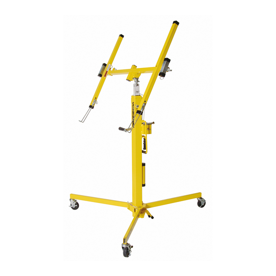
Cable Replacement Instructions for
Series 2311 & 2315 Single Cable Lifts
UK
US
Canada
Unit 16A
7514 Alabonson Road
75 Saltsman Drive, Unit 5
Blackpole Trading Estate East
Houston, TX 77088
Cambridge, ON N3H 4R7
Blackpole Road
1
phone: 281-999-6900
phone: 519-653-5300
Wocester WR3 8SG
fax: 281-999-6966
fax: 519-653-5305
phone: (44) 01905 458333
fax: (44) 01905 458222
Advertisement

Subscribe to Our Youtube Channel
Related Manuals for Sumner 2311 Series


Summary of Contents for Sumner 2311 Series
- Page 1 June 2012 Cable Replacement Instructions for Series 2311 & 2315 Single Cable Lifts Canada Unit 16A 7514 Alabonson Road 75 Saltsman Drive, Unit 5 Blackpole Trading Estate East Houston, TX 77088 Cambridge, ON N3H 4R7 Blackpole Road phone: 281-999-6900 phone: 519-653-5300 Wocester WR3 8SG fax: 281-999-6966 fax: 519-653-5305...
- Page 2 Step 1 Remove cradle and base from mast assembly. Lay down mast assembly on a solid level work sur- face. Step 2 Remove mast hold down assembly, (771055) screw and (772502) jam nut. Step 3 Remove (776042) screws and (784408) pulley guard.
- Page 3 Step 4 Remove (776042) screws and (774428) winch cover. Step 5 Remove (776042) screw from winch drum and remove cable as shown. Step 6 Remove top outer mast components as shown.
- Page 4 Step 7 Remove (771044) screws and (784403) top cover from both sides of the center mast tube. Step 8 Remove center mast assembly from the bottom of the outer mast. Step 9 Remove the pulley and wear pad from the bottom of the center mast.
- Page 5 Step 10 Pull cable from the loop position to a strait position through the bottom of the center mast for easy removal of top mast assembly. Step 11 Pull top mast assembly slightly out the bottom of the center mast as shown and remove all hardware.
- Page 6 Step 13 Remove (784399) center mast pulley weldment and (784398) pulley bracket from center mast. Step 14 Lay down all mast sections on a solid level work surface. Make sure all components required to assemble the 2300 lift are at hand. Step 15 Replace the damage load line as shown.
- Page 7 Step 16 Once cable is properly attach to the (784399) pulley weldment, give the cable the equal length of the center tube as shown. Step 17 Insert (784398) center mast pulley weldment on right side (working from the bottom) and (784398) pulley bracket in left side into the center mast tube as shown.
- Page 8 Step 18 Locate (771044) screws and secure the (784399) center mast pulley weldment and (784398) pulley bracket as shown. Use only one screw at this time. Step 19 Straight cable as shown. Make sure cable is not tangle up inside the mast section.
- Page 9 Step 21 Locate (784412) top mast wear discs, (784391) 2 “ pulley, (774041) dowel pin. Assemble components as shown. Step 22 Insert top mast assembly into center mast tube by pulling the cable and stop when the end of the top mast passes the second hole of the center mast tube.
- Page 10 Step 23 Insert and loop cable through the center mast slot as shown. Step 24 Locate (784404) center mast wear discs, (784390) 2-1/4” pulley, (774043) dowel pins and (784447) 1-5/8” pulley spacer. Assemble components as shown.
- Page 11 Step 25 Remove (771044) both screws on both sides from center mast tube. Step 26 Insert (774452) wear pads into slots on both sides as shown. Step 27 Insert center mast assembly into the bottom of the outer mast weldment.
- Page 12 Step 28 Insert end of cable through the outer mast weldment as shown. *Feed the cable all the way to the top of the outer mast. Step 29 Locate (771044) screws, (773550) 1/4 lock washers, (784403) top covers and assemble them in both sides of center mast as shown. *The lock washer goes on the single screw circled.
- Page 13 Step 30 Locate (772355) 3/8 lock nut, (771137) screw, (784394) 1/2” pulley spacer, (784390) 2-1/4” pulley, (784446) 2” spacer and assemble has shown. Step 31 Insert cable in drum and secure with (776042) screw as shown. *Once cable is secure wind the excess cable on the drum. Step 32 Locate (784408) pulley guard, (776042) screws and assemble as shown.
- Page 14 Step 33 Assemble (784428) winch cover and secure with (776042) screws. Step 34 Assemble mast hold down assembly into the top mast and secure with (771055) screw and (772502) jam nut. * Inspect and test unit after completion.
Need help?
Do you have a question about the 2311 Series and is the answer not in the manual?
Questions and answers