
Subscribe to Our Youtube Channel
Summary of Contents for Applied Robotics 1303-D05A
- Page 1 Robot Module 1303-D05A Tool Module 1304-D57A Tool Changer Safety Control Circuit Manual 95575 Rev 05 July 1, 2013 648 Saratoga Road Glenville, NY 12302 USA Phone: 518 384 1000 Fax: 518 384 1200...
- Page 2 The information and drawings contained herein are the sole property of Applied Robotics Incorporated and shall not be divulged to any third party without the prior written consent of Applied Robotics Inc. The information in this document is subject to change without notice. Applied Robotics makes no warranty of any kind with regard to this user’s guide, including but not limited to, implied warranties or fitness...
-
Page 3: Table Of Contents
1303-D05A & 1304-D57A Manual - 95575 Rev 05 Contents 1. Precautions ....................... 4 2. System Description .................... 5 3. State Diagram ....................6 4. Technical Specifications ..................7 5. Modules ......................8 6. Installation ......................9 6.1 Attachment to Tool Changer ..............9 6.2 Air Supply .................... -
Page 4: Precautions
1303-D05A & 1304-D57A Manual - 95575 Rev 05 1 Precautions READ MANUAL Do not start, operate or service machine until you read and understand operator's manual. Failure to do so could result in serious injury. HAND CRUSH NOTICE Indicates the possibility for a crush force between components during coupling of the Robot and Tool adaptor. -
Page 5: System Description
1303-D05A & 1304-D57A Manual - 95575 Rev 05 2 System Description Definitions Tool – A device that may be attached to a tool changer to perform a specific function Tool Changer – A device consisting of two adapters, one attached to a robot and one attached to a tool, that mechanically couple a robot to a tool, allowing a robot to use multiple tools. -
Page 6: State Diagram
1303-D05A & 1304-D57A Manual - 95575 Rev 05 Diagnostic Coverage The diagnostic coverage monitors the status of the Tool Stand Present, Tool Present, and the Output Valve Spool Position through a set of normally open and normally closed contacts. In order for proper opera- tion of the system, all dual channel devices need to operate simultaneously. -
Page 7: Technical Specifications
1303-D05A & 1304-D57A Manual - 95575 Rev 05 4 Technical Specifications Minimum Safety Classification Cat. 3 PLd EN ISO 13849-1 MTTFd 68 Years Mission Time 20a (20 years) Robot Side Dimensions 120mm x 118mm x 128mm Tool Side Dimensions 108mm x 59mm x 22mm... -
Page 8: Modules
1303-D05A & 1304-D57A Manual - 95575 Rev 05 5 Modules 1303-D05A S.1-EM-R-V-ISO 13849-SCM 1304-D57A S.1-EM-T-V-ISO 13849-SCM... -
Page 9: Installation
1303-D05A & 1304-D57A Manual - 95575 Rev 05 6 Installation 6.1 Attachment to Tool Changer With the Robot and Tool Adapter uncoupled and apart, install both the robot and tool side module on side one of the tool changer. 4 x ARI # 49798 SCR, SOC... -
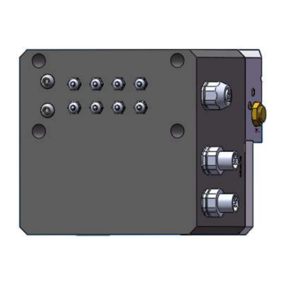
Page 10: Air Supply
1303-D05A & 1304-D57A Manual - 95575 Rev 05 6.2 Air Supply Connect the Air Supply to the 6mm air fitting show below: Upon supplying air to the Safety Control Module, the robot adaptor will be forced coupled. Make sure the tool adaptor is not within range of the robot side cams to cause an undesired couple. - Page 11 1303-D05A & 1304-D57A Manual - 95575 Rev 05 Power and Uncouple are supplied on two separate M12 connections J3 and J2, respectively. Connect the appro- priate cables to the connectors J3 and J2 as shown below: Make sure an uncouple signal is not being supplied by the cable you care connecting to J2.
-
Page 12: Manual Uncouple
1303-D05A & 1304-D57A Manual - 95575 Rev 05 7 Manual Uncouple With all cables and air fittings properly installed the Safety Module is ready for operation. Please refer to the system description on Page 5 and State Diagram on page 6 for how the module functions. During initial pro- gramming or if an undesired or abnormal state is achieved, the two M5 screws may be removed from the face of the cover to manually actuate the valves to uncouple. -
Page 13: Operational Guidelines
1303-D05A & 1304-D57A Manual - 95575 Rev 05 8.1 Operational Guidelines Review the guidelines below to understand how the Safety Control Module operates. Manual uncouple may be used in a case where a new tool is being installed and there is no tool stand pre- sent signal to interface with the Safety Control Module.
Need help?
Do you have a question about the 1303-D05A and is the answer not in the manual?
Questions and answers