Bunn AFPO-3 SL Service And Repair Manual
Bunn cold water dispenser product manual
Hide thumbs
Also See for AFPO-3 SL:
- Installation and operating manual (9 pages) ,
- Installation & operating manual (9 pages)
Table of Contents
Advertisement
Quick Links
SERVICE & REPAIR MANUAL
41093.0000A 04/08 ©2008 Bunn-O-Matic Corporation
L
F IL
R E
IN
M A
E R
W
P O
R
T E
W A
T
P U
IN
1
1
O R
A V
2
U T
F L
T P
O R
O U
A V
F L
P U
T
IN
R
2
T E
W A
U T
T P
O U
O R
A V
U T
F L
T P
O U
R
T E
W A
U T
T P
O U
BUNN-O-MATIC CORPORATION
POST OFFICE BOX 3227
SPRINGFIELD, ILLINOIS 62708-3227
PHONE: (217) 529-6601 FAX: (217) 529-6644
AFPO-2 SL
AFPO-3 SL
1
2
O R
A V
U T
F L
T P
O U
R
T E
U T
W A
T P
O U
AFPO-2
AFPO-3
1
1
O R
O R
A V
F L
A V
T
2
U T
P U
F L
T P
IN
O U
2
R
T E
U T
W A
T P
3
O U
O R
A V
U T
F L
T P
O U
3
R
T E
U T
W A
T P
O U
1
2
L
F IL
R E
3
IN
M A
E R
W
P O
R
T E
W A
T
P U
IN
Advertisement
Table of Contents

Related Manuals for Bunn AFPO-3 SL


Summary of Contents for Bunn AFPO-3 SL
- Page 1 SERVICE & REPAIR MANUAL BUNN-O-MATIC CORPORATION PHONE: (217) 529-6601 FAX: (217) 529-6644 41093.0000A 04/08 ©2008 Bunn-O-Matic Corporation F IL POST OFFICE BOX 3227 SPRINGFIELD, ILLINOIS 62708-3227 AFPO-2 SL AFPO-3 AFPO-3 SL F IL...
- Page 2 SOLE OPTION AS SPECIFIED HEREIN, TO REPAIR, REPLACEMENT OR REFUND. In no event shall BUNN be liable for any other damage or loss, including, but not limited to, lost profits, lost sales, loss of use of equipment, claims of Buyer’s customers, cost of capital, cost of down time, cost of substitute equipment, facilities or services, or any other special, incidental or consequential damages.
-
Page 3: Table Of Contents
User Notices ...3 Preventive Maintenance Cleaning ...4 Adjustments ...4 Operating Controls ...6 Troubleshooting ...7 Service ...9 Circuit Board ...10 Fuse & Fuse Holder ... 11 Main ON/OFF Switch ... 12 Probe LOW/OFF/HIGH Switches ... 13 Pump (Flavor) Start Switches ... 14 Refill ON/OFF Switches ... -
Page 4: Cleaning
CLEANING RECOMMENDED WEEKLY CLEANING: This should be done in conjunction with the recommended weekly cleaning of your machine. The Hoppers must be empty before starting. 1. Prepare a 1 gallon cleaning solution consisting of 1 gallon of hot water and a sanitizing cleaner which contains 3-5% chlorine based sanitizer. -
Page 5: Needle Valve
MIX RATIO ADJUSTMENTS(cont.) Mix ratio (water/flavor) Time for FLAVOR OUTPUT (1/2 cup) assume 20 sec. or obtain time per note below assume 20 sec. or obtain time per note below assume 20 sec. or obtain time per note below 4+1(see below) assume 20 sec. -
Page 6: Main Power On/Off
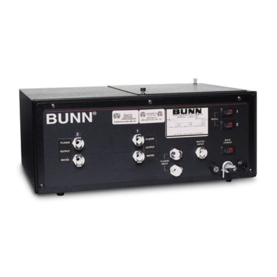
A. MAIN POWER ON/OFF The main power ON/OFF switch is located on the right of the front panel just above the power cord. B. REFILL CIRCUIT ON/OFF The refill circuit ON/OFF switches are located on the right of the front panel just above the main power switch. These allow each circuit to operate independently. -
Page 7: Troubleshooting
A troubleshooting guide is provided to suggest probable causes and remedies for the most likely problems encountered. If the problem remains after exhausting the troubleshooting steps, contact the Bunn-O-Matic Technical Service Department. • Inspection, testing, and repair of electrical equipment should be performed only by qualified service person- nel. -
Page 8: Circuit Board
TROUBLESHOOTING (cont.) PROBLEM Product will not dispense (cont.) Incorrect mix ratio Motor thermal cutout (motor stops running) NOTE: This refill unit should not be used to initially fill the hopper. Running the motor for extended periods will trip the thermal switch. The thermal switch will reset, but requires up to 30 minutes of cooling time. PROBABLE CAUSE 6. -
Page 9: Component Access
SERVICE This section provides procedures for testing and replacing various major components used in this dispenser should service become necessary. Refer to Troubleshooting for assistance in determining the cause of any problem. WARNING - Inspection, testing, and repair of electri- cal equipment should be performed only by qualified service personnel. -
Page 10: Circuit Board
SERVICE CIRCUIT BOARD FIG. 2 CIRCUIT BOARD Location: The circuit board is located inside the autofill box, mounted on the right side of the solenoid mounting bracket under the switch panel. Test Procedure: 1. Disconnect the dispenser from the power source. 2. -
Page 11: Fuse And Fuse Holder
SERVICE FUSE AND FUSE HOLDER FIG. 4 FUSE HOLDER Location: The fuse holder is located on the lower right front of the autofill box just to the left of the power cord. Test Procedure: 1. Disconnect the dispenser from the power source. 2. -
Page 12: Main On/Off Switch
SERVICE (cont.) MAIN ON/OFF SWITCH FIG. 6 MAIN ON/OFF SWITCH Location: The main ON/OFF switch is located on the lower right front of the autofill box just above the power cord. Test Procedure: 1. Disconnect the dispenser from the power source. -
Page 13: Probe System
SERVICE (cont.) PROBE SYSTEM FIG. 8 PROBE SWITCHES Location The probe switches are located on the rear of each hopper, mounted in the probe housing cover. Test Procedure Probe System 1. Disconnect the dispenser from the power source. 2. With the probe boxes connected to the signal cable, remove connector from refill box. - Page 14 SERVICE (cont.) PUMP (FLAVOR) ON/OFF SWITCHES FIG.12 PUMP (FLAVOR) START SWITCHES Location: The pump (flavor) START switches are located on the switch mounting plate inside the autofill box on the right side. Test Procedure: 1. Disconnect the dispenser from the power source.
-
Page 15: Refill On/Off Switches
SERVICE (cont.) REFILL SWITCHES FIG. 14 REFILL SWITCHES Location: The refill switches are located on the upper right front of the autofill box. Test Procedures: 1. Disconnect the dispenser from the power source. 2. Disconnect the two white/red, brown/black or red/black wires from the switch terminals. - Page 16 SERVICE (cont.) SOLENOIDS FIG. 16 SOLENOIDS Location: The solenoids are located inside the autofill box. Test Procedure: 1. Disconnect the dispenser from the power source. 2. Disconnect the white/violet, violet or blue wire and the white wire from the solenoid. 3.
-
Page 17: Solenoid
SERVICE (cont.) SOLENOID (WATER) ON/OFF SWITCHES FIG.18 SOLENOID (WATER) ON/OFF SWITCHES Location: The solenoid (water) ON/OFF switches are located on the switch mounting plate inside the autofill box on the right side. Test Procedure: 1. Disconnect the dispenser from the power source. 2. -
Page 18: Test/Operate Switch
SERVICE (cont.) TEST/OPERATE ON/OFF SWITCH FIG. 20 TEST/OPERATE SWITCH Location The test/operate switch is located inside the autofill box on the right side. Test Procedures: 1. Disconnect the dispenser from the power source. 2. Remove the black wire from the top center switch terminal. -
Page 19: Vacuum/Supply Pump Assembly
SERVICE (cont.) VACUUM/SUPPLY PUMP ASSEMBLY FIG. 22 VACUUM/SUPPLY PUMP ASSEMBLY Location: The vacuum/supply pumps are located inside the autofill box. Test Procedure: 1. Disconnect the dispenser from the power source. 2. Disconnect the white wire from the pump lead and the yellow, orange or red wire from the other lead. - Page 20 SERVICE (cont.) VACUUM/SUPPLY PUMP TUBE INSTALLATION 2. Separate the two halves of the pump and carefully remove the tubing from within. 3. Hold the new pump head as shown in Fig. 24, with rollers in the 2, 6, and 10 o’clock positions. 4.
-
Page 21: Vacuum Switches
SERVICE (cont.) VACUUM SWITCHES FIG. 26 VACUUM SWITCHES Location: The vacuum switches are located inside autofill box, mounted on the left side of the solenoid mounting bracket just below the needle valves. Test Procedure: 1. Disconnect the dispenser from the power source. -
Page 22: Piping Diagram
PIPING DIAGRAM (AFPO-2) The only difference between the AFPO-2/3 and AFPO-2/3 SL is the SL models have a water output line and a flavor output line for each product. This allows the water and flavor to be mixed in the hoppers. Refer to the illustration below when connecting the lines. -
Page 23: Wiring Diagrams
SOLENOID SWITCH #2 PUMP SW ITCH #1 RED/BLK PUMP J4-1 BRN/BLK RED/BLK J4-10 120 VOLT AC 2 WIRE SINGLE PHASE 28814.0000D 6/98 ©1998 BUNN-O-MATIC CORPORATION AFPO-2 SW1D REFILL ON/OFF SWITCH #2 BRN/BLK SW1C REFILL ON/OFF SWITCH #1 RED/BLK SW1B SW1A... - Page 24 41093 040408...
-
Page 25: Schematic Wiring Diagram
SOLENOID SWITCH #2 PUMP SW ITCH #1 RED/BLK PUMP J4-1 BRN/BLK RED/BLK J4-10 230 VOLT AC 2 WIRE SINGLE PHASE 28814.0004A 11/99 ©1999 BUNN-O-MATIC CORPORATION AFPOA-2 SW1D REFILL ON/OFF SWITCH #2 BRN/BLK SW1C REFILL ON/OFF SWITCH #1 RED/BLK SW1B SW1A...
Need help?
Do you have a question about the AFPO-3 SL and is the answer not in the manual?
Questions and answers