
Related Manuals for Kentec Electronics Sigma A-CP


Summary of Contents for Kentec Electronics Sigma A-CP
- Page 1 Sigma A-CP Conventional Fire Control Panel Installation and Operation Manual Man-1194 Issue 04 February 2014 www.acornfiresecurity.com...
- Page 2 File number (S 8485) Fire Alarm Equipment Kentec Electronics Ltd. Models K1842-XY, K1844-XY and K1848-XY of the Sigma A-CP Fire Control Panel are suitable as follows: Without integrated dialer and conventional detection for 2, 4 or 8 zones. ...
- Page 3 Copyright © 2014 by Kentec Electronics Ltd. All rights reserved. Kentec is a registered trademark of Kentec Electronics Ltd. All other product or service names are property of their respective owners. www.acornfiresecurity.com...
-
Page 4: Table Of Contents
Damaged Goods ..................................... 3 Component Failure ....................................4 Service Replacement Items.................................. 4 Out of Warranty Items ................................... 5 Items Returned For Credit ..................................5 Kentec Electronics Ltd......................6 Section 2 Overview Hardware Features ........................9 Internal Power Supply ..................................10 Panel Controls and Indicators ................................ - Page 5 www.acornfiresecurity.com Separation of Circuits ......................24 AC Cabling ..........................25 Standby-Battery Cabling ......................26 Field Cabling.......................... 28 Detection Zones ....................................28 ALM RES ........................................30 Notification Appliance Circuits (NAC) s ............................30 Relay Outputs ......................................31 Optional Dialer Board ..................................31 Aux 24V ........................................
- Page 6 www.acornfiresecurity.com Section 5 Maintenance and Repair Cleaning the External Cabinet and Fascia-Door ..............58 Inspecting Batteries ....................... 58 Replacing Standby-Batteries ....................58 Removing the Standby-Batteries ..............................58 Installing the Standby-Batteries ..............................59 Replacing Fuses ........................59 Battery Fuse ......................................59 Transformer Fuse ....................................
- Page 7 Appendix B Equipment List Sigma A-CP Fire Control Panels ....................71 Supporting Components and Replacements ................72 Detectors ..........................74 Apollo ........................................74 System Sensor ....................................... 74 Hochiki ........................................75 Notification Appliances ..................................75 Appendix C Calculations Determining the Amp-Hour Rating ..................91 Current-Load ......................................
-
Page 8: Introduction
Section 1 Introduction This manual describes conventional detection models of the Sigma A-CP Fire Control Panel. These models can include or exclude dialer communication. Models including dialer communication are the 2 zone K1852, 4 zone K1854 and 8 zone K1858. -
Page 9: Using This Manual
Alarm Conditions, Controls and Indicators, understand Relay Contacts and how to Configure Ancillary Circuit Boards. Section 5 Maintenance and Repair describes how to maintain and repair the Sigma A-CP Fire Control Panel. Appendix A Specifications provide characteristics of the Sigma A-CP Fire Control Panel. -
Page 10: Document Conventions
In the event of damage to equipment during transit or any defect in the quality of goods, the Buyer shall notify Kentec Electronics Ltd within seven days of delivery as detailed in Section 8.5 of the Terms & Conditions of Sale. The goods may then be returned to the Customer Service Department of Kentec Electronics Ltd. -
Page 11: Component Failure
SRI parts are loan items and are not available for resale. At all times, Kentec Electronics Ltd. retains the title of SRI parts supplied, as detailed in Section 7.4 of the Terms and Conditions of Sale. -
Page 12: Out Of Warranty Items
Items Returned For Credit Items shall only be accepted for credit by written approval with the Operations Manager or Directors of Kentec Electronics Ltd. Items will only be eligible for credit in the first 3 months from the supply date. -
Page 13: Kentec Electronics Ltd
Goods must be returned to Kentec Electronics Ltd within 30 days of the issue of the Goods Return Application Form. Only items listed on this from must be returned under the RMA reference. Items returned without prior request for an RMA reference may be returned to the customer. -
Page 14: Overview
Section 2 Overview The Sigma A-CP Fire Control Panel is a conventional fire control panel with features for operating detection zones, Notification Appliance Circuits (NACs), relays and auxiliary 24 volt power. Models of the Sigma A-CP Fire Control Panel support synchronization protocols from Wheelock, Gentex, Amseco and System Sensor. - Page 15 All models accept standby-batteries and contain a power supply with an internal battery charger. Models of the Sigma A-CP Fire Control Panel accept 7 AH or 12 AH valve-regulated, lead-acid batteries and operate in special application modes for power inputs of 115 VAC or 230 VAC.
-
Page 16: Hardware Features
Hardware Features The figure below illustrates hardware features of the Sigma A-CP Fire Control Panel: Figure 2-2 Hardware Features FUSE 7 A/H BATTERY 12 AH Battery 7 A/H BATTERY 7 A/H BATTERY 12 AH Battery Item Description Main Terminal Block... -
Page 17: Internal Power Supply
Power Outputs The Sigma A-CP Fire Control Panel provides power outputs to the terminals of NAC 1, NAC 2, and AUX 24V terminals. Reference Section 3, Installation and Appendix A, Specifications for further information concerning NAC and AUX 24V outputs of the Sigma A-CP Fire Control Panel. -
Page 18: Panel Controls And Indicators
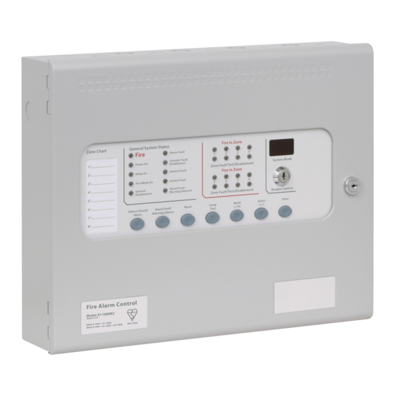
Panel Controls and Indicators The fascia of the Sigma A-CP Fire Control Panel is divided into sections for controls and indicators. The figure below illustrates controls and indicators of the Sigma A-CP Fire Control Panel: Figure 2-3 Controls and Indicators... - Page 19 Upper Indicators The figure below illustrates upper indicators of the Sigma A-CP Fire Control Panel: Figure 2-4 Upper Indicators General System Status Alarm In Zone Fire Supervisory NAC Trouble AC Power On Disabled Mode Trouble/Test/Disablement Delay On General Trouble...
- Page 20 www.acornfiresecurity.com Upper Indicators LED Color Alarm In Zone 1 Trouble/Test/Disablement Yellow Alarm 2 Trouble/Test/Disablement Yellow Alarm 3 Trouble/Test/Disablement Yellow Alarm 4 Trouble/Test/Disablement Yellow Alarm Alarm In Zone 5 Trouble/Test/Disablement Yellow Alarm 6 Trouble/Test/Disablement Yellow Alarm 7 Trouble/Test/Disablement Yellow Alarm 8 Trouble/Test/Disablement Yellow Alarm Two Seven-Segment LEDs...
- Page 21 Access Level 2. Trouble events are non-latching inputs and cannot be cleared by the Reset button. Non-latching inputs are cleared when faults are cleared. Lamp Test Tests fascia indicators and the internal buzzer of the Sigma A-CP Fire Control Panel by illuminating all LEDs while sounding the buzzer. Mode (+10) Changes the tenths position on the numeric Mode display for programming configuration codes.
- Page 22 Lower Indicators The figure below illustrates the lower indicators of the Sigma A-CP Fire Control Panel: Figure 2-6 Lower Indicators W/Dog Mains Batt. Aux.24V Batt. Comms Earth Sys.Fuse NAC1 NAC2 Fail Fail Trbl. Trbl. Trbl. Trbl. Trbl. Trbl. Trbl.
- Page 23 Upper Controls The figure below illustrates upper controls of the Sigma A-CP Fire Control Panel: Figure 2-7 Upper Control General System Status Alarm In Zone Fire Supervisory NAC Trouble AC Power On Disabled Mode Trouble/Test/Disablement Delay On General Trouble...
-
Page 24: Field Terminals
Field Terminals The figure below illustrates field terminals of the Sigma A-CP Fire Control Panel: Figure 2-9 Field Terminals NC C NC C NC C NAC POWER POWER AUX 24V ALM RES RS485 NAC1 NAC2 Z1 RET TRBL SUPV. - Page 25 Contacts of the fire relay (FIRE) support a maximum load of 1 Amp with voltage free change-over. DIALER BOARD Provides two pairs of connections for line and phone with tip and ring features. CONNECTIONS The Dialer Board is an optional feature on models of the Sigma A-CP Fire Control Panel. www.acornfiresecurity.com...
-
Page 26: Optional Dialer Board
The Dialer Board is an optional DAC (Digital Alarm Communicator) feature provided on specific models of the Sigma A-CP Fire Control Panel. The Optional Dialer Board connects to the Main Board of the fire control panel and communicates status and alarm conditions to digital receivers. -
Page 27: Installation
Section 3 Installation This section provides instructions for connecting cables, mounting and testing the Sigma A-CP Fire Control Panel for installation. Install this product in accordance with NFPA 72, the National Electrical Code and all local codes. General Installation Checklist To complete the installation: Create a plan for the fire alarm system and provide a checklist for installing the fire control panel. -
Page 28: Before You Begin
Create a plan and checklist before beginning the installation process. Planning can reduce the number of problems that can occur during installation. Select a mounting site that is a suitable operating environment for the Sigma A-CP Fire Control Panel. The mounting site chosen should be clean, dry and not subject to shock or vibration. -
Page 29: Determining System Current Draw
Sigma A-CP Fire Control Panel. Mounting the Fire Control Panel This section describes preparing, removing the fascia and mounting the Sigma A-CP Fire Control Panel. Preparing Complete the following steps to prepare the fire control panel for mounting: Open the cabinet-door of the fire control panel using the door-lock-key. -
Page 30: Removing The Fascia
Removing the Fascia Remove the fascia of the Sigma A-CP Fire Control Panel prior to the mounting process to prevent damage to circuit board components. To remove the fascia from the cabinet-box of the Sigma A-CP Fire Control Panel: Remove the mounting-screw on the right-side of the fascia. -
Page 31: Separation Of Circuits
¼ inch spacing between non-power and power limited circuit conductors. All circuits of the Sigma A-CP Fire Control Panel are power limited accept AC input, AC output, battery, transformer input, transformer output, bridge rectifier input and bridge rectifier output. -
Page 32: Ac Cabling
12 AH Battery AC Cabling Power cabling from the mains to the Sigma A-CP Fire Control Panel must provide connections to branch circuits containing a 15 Amp fuse. Specify 14 AWG wiring for this connection. Power cabling must enter the back, top or left-side of the fire control panel cabinet through the cabinet-knockouts. -
Page 33: Standby-Battery Cabling
Connect AC cabling from the power-source to the main terminal block. The main terminal block is located on the top-left of the Sigma A-CP Fire Control Panel. Wiring from the power-source must include a secure earth-ground connection from the building-ground to the fire control panel and must enter the fire control panel cabinet as close as possible to the main terminal block. - Page 34 Positive Battery Lead ( Red Cable ) Jumper-Lead Negative Battery Lead ( Black Cable ) 12 AH Battery 12 AH Battery The series connection illustrated provides a standby voltage of 24 VDC required by the Sigma A-CP Fire Control Panel. www.acornfiresecurity.com...
-
Page 35: Field Cabling
Zones of the Sigma A-CP Fire Control Panel operate NFPA 72 Class B, Style C or NFPA 72, Class B, Style B. Style C devices provide trouble conditions for direct shorts and opens on zone loops. Style B devices provide alarm conditions for direct shorts and trouble conditions for opens on zone loops. - Page 36 (EOLR) Zone Zones of the Sigma A-CP Fire Control Panel are not listed to operate more than one detector in the alarm condition. Reference Appendix B, Detectors for the maximum number of devices permitted per circuit. The value provided identifies the maximum number of devices permitted to operate on the zone circuit.
-
Page 37: Alm Res
NAC devices are connected to these NAC outputs. NAC 1 and NAC 2 The Sigma A-CP Fire Control Panel provides synchronized outputs on NAC 1 and NAC 2 with built-in synchronized protocols. These terminals are authorized for special application or synchronized pulsed DC output voltage. -
Page 38: Relay Outputs
Reference Appendix A, Specifications for relay ratings of Sigma A-CP Fire Control Panel. Optional Dialer Board The Optional Dialer Board is an optional feature provided on specific models of the Sigma A-CP Fire Control Panel. Mount the Optional Dialer Board on the Main Board of the Sigma A-CP Fire Control Panel. - Page 39 Installation To mount the Optional Dialer Board of the Sigma A-CP Fire Control Panel: Locate the left area of the Main Board to connect and secure the Optional Dialer Board. The left area of the Main Board contains fuse F3, internal buzzer BZ1 and connector J1.
- Page 40 DIALER BOARD CONNECTIONS Mode Reference Appendix B, Equipment List for Sigma A-CP Fire Control Panel models supporting the Optional Dialer Board. Reference Appendix A, Specifications for wire gages acceptable for these terminal block connections. S i g m a A - C P F i r e C o n t r o l P a n e l - I n s t a l l a t i o n a n d O p e r a t i o n M a n u a l M a n - 1 1 9 4 ( K 1 8 6 1 - 0 0 ) , R e v i s i o n E 0 1 .
- Page 41 www.acornfiresecurity.com TELCO Line Connections The figure below illustrates TELCO line 1 and line 2 connections of the Optional Dialer Board: Figure 3- 12 TELCO Line Connections Telephone Line 1 IN Telephone Line 2 IN Brown Brown Green Green Phone 1 Phone 2 Gray Gray...
-
Page 42: Aux 24V
www.acornfiresecurity.com Aux 24V The AUX 24V connection is a common DC voltage and special application output. The output is supervised for short-circuits and ground faults. The output is not supervised for open circuit conditions. Terminals of the Aux 24V output are labeled positive ( + ) and negative ( - ). Operating Limits The AUX 24V supply is protected by an electronic, self-resetting fuse rated at 1.1 A. -
Page 43: Testing The Installation
Program and test the configuration to ensure that the control panel operates as intended. Troubleshooting Troubleshoot the Sigma A-CP Fire Control Panel when conflicts exist after installing or configuring. Monitor the lower fascia indicators of the fire control panel to determine the cause of the trouble condition. - Page 44 www.acornfiresecurity.com Indicator Description Batt Low Illuminates when the fire control panel is operating on batteries and the battery voltage is below 21.5 VDC. Illuminates when the fire control panel is operating on AC and the battery voltage is below 24 VDC. Comms Trbl Communication has been lost with the remote annunciator or Ancillary board.
-
Page 45: Programming And Operating
www.acornfiresecurity.com Section 4 Programming and Operating Notice to Users, Installers, Authorities Having Jurisdiction, and other involved parties. This product incorporates field-programmable software. In order for the product to comply with the requirements in the Standard for Control Units and Accessories for Fire Alarm Systems, UL 864 10th Edition, certain programming features or options must be limited to specific values or not used at all as indicated below. - Page 46 www.acornfiresecurity.com Program Feature or Option Permitted in UL 864 Possible Settings Settings Permitted ? (Y / N) In UL 864 Remove AUX 24V Set / Clear Set / Clear On Fire Alarm Code: 28 Set Z1-Z8, Zone Alarm Delayed Set / Clear for each Clear all zones Code: 31 - 38 zone...
-
Page 47: Programming The Fire Control Panel
The Mode LED display on the fascia of the fire control panel provides the configuration menu. Open the menu through Access Level 2 and Access Level 3 of the Sigma A-CP Fire Control Panel. Open Access Level 2 by turning the Enable Access key to the right. Open Access Level 3 by moving the Write Enable slide-switch to the left. -
Page 48: Navigate The Menu
Navigate the menu on the Mode LED display using the Mode (+10), Select (+1) and Enter buttons of the Sigma A-CP Fire Control Panel. The Mode LED, Mode (+10), Select (+1) and Enter buttons are located on the center of the fascia. - Page 49 Programming Default Settings Program codes 00 and 10 to complete default setting requirements of the Sigma A-CP Fire Control Panel. To program default settings of the fire control panel: Turn the Enable Access key to the right to enter Access Level 2.
- Page 50 The figure below illustrates the Write Enable switch on the fascia of the Sigma A-CP Fire Control Panel: Figure 4- 3 Write Enable Slide-Switch Code 00 is displayed on the menu of the Mode LED after entering Access Level 3.
- Page 51 www.acornfiresecurity.com Press Mode (+10) on the fascia to scroll from code 00 to 10 on the menu. Choose code 10 from the menu and press Enter to set the code. A flashing dot is displayed in the lower-right-corner of the Mode LED to identify the set code. The figure below illustrates a code 10 set and a code 10 not set in the menu: Figure 4- 5 Code 10 Set and Code 10 Not Set...
-
Page 52: Configuration Codes
Configuration Codes Not all configuration codes of the Sigma A-CP Fire Control Panel are authorized for operation under UL 864. Reference Appendix G, UL 864 Permitted Configurations for the list of authorized configuration codes of the Sigma A-CP Fire Control Panel. - Page 53 www.acornfiresecurity.com Code Function Description Set Amseco Alarm Mode Sets the fire control panel to operate NAC devices from Amseco. Set Gentex Alarm Mode Sets the fire control panel to operate NAC devices from Gentex. Set System Sensor Alarm Mode Sets the fire control panel to operate NAC devices from System Sensor.
- Page 54 www.acornfiresecurity.com Code Function Description Set Z1, Alarm Delayed These functions are not UL recognized. Sets an alarm delay from the detector to the zone Set Z2, Alarm Delayed based on Alarm Delay codes 0-9. Program these functions to operate by setting code Ad in Access Set Z3, Alarm Delayed Level 2.
- Page 55 www.acornfiresecurity.com Code Function Description Set Z3, Coincidence Set Z4, Coincidence Set Z5, Coincidence Set Z6, Coincidence Set Z7, Coincidence Set Z8, Coincidence Set Z1, Configure I.S. Barrier These functions are not UL recognized. Set this function to configure the Zone I.S. Barrier. Set Z2, Configure I.S.
- Page 56 www.acornfiresecurity.com Code Function Description Set Z7, Short Circuit Triggers Alarm Set Z8, Short Circuit Triggers Alarm Set Z1, Non-Latching These functions are UL recognized for zones reporting supervisory conditions. Set Z2, Non-Latching These functions are not UL recognized for zones reporting fire conditions.
- Page 57 www.acornfiresecurity.com Code Function Description Set Z1, Alarm Must Persist for 30 Seconds These codes set 30 second alarm duration before reporting. Alarm must persist for 30 seconds before conditions are reported. Set Z2, Alarm Must Persist for 30 Seconds These codes are used when a device could report a Set Z3, Alarm Must Persist for 30 Seconds condition unintentionally.
- Page 58 Functions and Codes Functions and codes for operating the Sigma A-CP Fire Control Panel in Access Level 2 are described below: Function Terminal Codes Description Test Zones Select codes t1 through t8 to place Zones 1 through 8 in Test Mode. Zones in Test Mode automatically reset 3 seconds after operating.
-
Page 59: Control Operation
Delay Delay function and codes 31-38 of the Zone Alarm Delayed function. Control Operation The table below describes control operation of the Sigma A-CP Fire Control Panel: Controls Operation W / Dog Reset Press the W / Dog Reset button to clear the watchdog event. The watchdog event causes a reset when the fire control panel fails to carry out an operation. -
Page 60: Single Zone Fire Condition
NACs to operate again. The NACs can be toggled on and off with the Silence/Sound alarm button as required. Reset The reset command restores operation of the Sigma A-CP Fire Control Panel from an alarm or trouble condition. Zone Trouble Removal of a detector from its base or a trouble on any of the zone wiring will cause the Trouble LED and Zone Trouble LEDs to flash, indicating the zone in which the trouble has occurred. -
Page 61: General Trouble
www.acornfiresecurity.com General Trouble The General Trouble LED illuminates during all trouble conditions. The LED also lights when the Enable Access key has been removed while in Access Level 3. Lamp Test All LED indicators can be tested at any time by pressing the Lamp Test button. Access Level 2 is not required to perform the Lamp Test. -
Page 62: Disablements
Re-enable zones following the disabling process. Disabling Zones To disable zones on the Sigma A-CP Fire Control Panel: Turn the Enable Access key to the right to obtain Access Level 2 of the menu. Press Mode (+10) until “d1” appears in the first field of the LED display. -
Page 63: Alarm Delays
www.acornfiresecurity.com Turn the Enable Access key to the left to exit Access Level 2. The Trouble/ Test /Disablement LEDs, Disablement LED and Mode LED are no longer lit. Disable NAC Outputs To disable NAC outputs: Turn the Enable Access key to the right to open Access Level 2. Press the mode button to select “db”... -
Page 64: Relay Operation
Reference Default Operation before programming these alarm delay settings. Relay Operation The Sigma A-CP Fire Control Panel provides volt free changeover relay contacts for local control and signaling. The relay contacts are rated for switching signaling circuits only and the maximum ratings should not be exceeded under any circumstances. -
Page 65: Cleaning The External Cabinet And Fascia-Door
Cleaning the External Cabinet and Fascia-Door Clean the external cabinet and fascia-door of the Sigma A-CP Fire Control Panel with a damp cloth. Do not clean these surfaces with detergents or solvents. Do not permit water to enter the cabinet during the cleaning process. -
Page 66: Installing The Standby-Batteries
Reference Section 3, Installation for installing the standby-batteries. Replacing Fuses The Sigma A-CP Fire Control Panel contains a battery fuse, a transformer fuse and an AC input fuse to protect it against circuit overloads. A 6.3 Amp slow-blow fuse protects the battery charging circuit and the transformer secondary. -
Page 67: Transformer Fuse
Re-connect the red-lead of the recharging circuit to the positive terminal of the standby-batteries. Close the fascia-door of the Sigma A-CP Fire Control Panel. Connect NAC Power and Power inserts from the fascia terminal strip of the Sigma A-CP Fire Control Panel. Turn on 115 VAC or 230 VAC at the power source. -
Page 68: Ac Input Fuse
Disconnect the red-lead of the recharging circuit from the positive terminal of the standby-battery. Remove NAC Power and Power inserts from the fascia terminal strip of the Sigma A-CP Fire Control Panel. Remove the retaining-screw securing the fascia to the cabinet of the Sigma A-CP Fire Control Panel. -
Page 69: Replacing Cabinet Components
Secure the retaining-screw to the fascia-door and the cabinet of the Sigma A-CP Fire Control Panel. Connect NAC Power and Power inserts from the fascia terminal strip of the Sigma A-CP Fire Control Panel. Secure the retaining-screw to the fascia-door and the cabinet of the Sigma A-CP Fire Control Panel. -
Page 70: Specifications
Appendix A Specifications This appendix provides electrical and environmental specifications of the Sigma A-CP Fire Control Panel. Electrical AC Line Connection Terminals Description Voltage AC Line 115 VAC @ 50 / 60Hz (Supervised), 170 VA Maximum 230 VAC @ 50 / 60Hz (Supervised) ), 170 VA Maximum... -
Page 71: Maximum Current Draw
Maximum Current Draw The maximum current draw of the Sigma A-CP Fire Control Panel cannot exceed 5.18 A. Outputs of the fire control panel can be loaded with combinations of currents as long as the total does not exceed 4.5 A. - Page 72 Current Loading Limitations Standby-batteries of the Sigma A-CP Fire Control Panel are rated for 7 AH or 12 AH of operation. Standby and alarm current of the Sigma A-CP Fire Control Panel can include all or part of the following loads:...
-
Page 73: Field Wiring
Current loading calculations do not include the combined IDC currents of the Sigma A-CP Fire Control Panel. These combined IDC currents are negligible in comparison to fire control panel, ancillary device and NAC currents of the Sigma A-CP Fire Control Panel and are therefore excluded from the current loading calculation. - Page 74 Battery leads are provided in the cabinet for recharging the standby-batteries. One end of the battery leads are permanently connected to the power supply of the Sigma A-CP Fire Control Panel. The opposite end of the battery leads connect to terminals of the standby-batteries.
-
Page 75: Initiating Device Circuit (Idc) Ratings
Reference Appendix B, Equipment List, Detectors Zones 1 through 8 The maximum line impedance shown in the IDC Ratings table represents all initiating circuit types on detection zones of The Sigma A-CP Fire Control Panel. Notification Appliance Circuit (NAC) Terminal... -
Page 76: Relay Ratings
AUX 24V Terminal Rating AUX 24V (+ / -) 15 - 28 VDC, special application, 500 mA maximum ALM RES ALM RES inputs are unused on the Sigma A-CP Fire Control Panel: Terminal Description No Connection (NC) TRBL Dialer Board... -
Page 77: Cabling
Cabling Grounding Conductor Install ground conductors with 14 AWG cabling to support branch circuits of the Sigma A-CP Fire Control Panel. Branch Circuits Protect branch circuits from the AC power source with a 15 Amp fuse. Material All field wiring should be installed using fire rated cables according to the NFPA except AC and TELCO. -
Page 78: Equipment List
Appendix B Equipment List This appendix describes models of the Sigma A-CP Fire Control Panel, supporting equipment and devices. Sigma A-CP Fire Control Panels The following models are provided for the Sigma A-CP Fire Control Panel: Models Features K1842-10... -
Page 79: Supporting Components And Replacements
K1858-40 8 Zone Conventional Panel with Dialer, Gray, 115V K1858-41 8 Zone Conventional Panel with Dialer, Gray, 230V Supporting Components and Replacements The following supporting components and replacements are available for the Sigma A-CP Fire Control Panel: Model Description Man-1194... - Page 80 www.acornfiresecurity.com Model Description K18040-00 Dialer Configuration Utility Manual K1850-00 Dialer Board K1842-00 2 Zone Board K1844-00 4 Zone Board K1848-00 8 Zone Board K1897-00 470 Ohm Resistor (1), Trigger Resistor K1898-00 270 Ohm Resistor (1), Series Resistor K1895-00 10K Ohm Resistor (1): Sleeved End of Line (EOL) resistor K1896-00 6.8K Ohm Resistor (1): Sleeved End of Line (EOL) resistor K5450-00...
-
Page 81: Detectors
Detector models from Apollo, Hochiki and System Sensor must not be mixed on individual zones of the Sigma A-CP Fire Control Panel. Detector models from these manufacturers can be mixed between separate zones of the fire control panel as long as each zone contains detectors from a single manufacturer. -
Page 82: Hochiki
NS6-220 Notification Appliances Outputs of NAC 1 and NAC 2 on the Sigma A-CP Fire Control Panel operate in a special application mode. The special application mode conforms to specific levels of continuous DC. Outputs meet these requirements when NAC currents do not exceed 2.5 A on NAC 1 or NAC 2 with the combined currents not to exceed 4 A. - Page 83 The Sigma A-CP Fire Control Panel can also safely operate combinations of device-loads on NAC 1 and NAC 2. These device-loads can include combinations such as strobes, horns, strobe/chimes, strobe/horns and speaker strobes.
- Page 84 www.acornfiresecurity.com The following series of Amseco NAC devices are compatible for use on the special application outputs of NAC 1 and NAC 2 when operating each NAC output below 2.5 A: Name of Series Environment Model Series Description Mounting Type Select-A-Strobe/Chime Indoor CM24C...
- Page 85 www.acornfiresecurity.com Name of Series Environment Model Series Description Mounting Type Select-A-Strobe/Chime Indoor SCM24W-75110 Chime Strobe Wall Select-A-Horn Indoor H24W Horn Wall/Ceiling Select-A-Strobe/Horn Indoor SH24W-1530 Horn Strobe Wall Select-A-Strobe/Horn Indoor SH24W-75110 Horn Strobe Wall Indoor/Outdoor Horn/ Indoor/Outdoor SHB24-75 Horn Strobe Wall Strobe Speaker/Strobe Indoor...
- Page 86 The Sigma A-CP Fire Control Panel can also safely operate combinations of device-loads on NAC 1 and NAC 2. These device-loads can include combinations such as strobes, horns, strobe/chimes, strobe/horns and speaker strobes.
- Page 87 NAC outputs of the Sigma A-CP Fire Control Panel are not limited by conditions other than the maximum rated current threshold. NAC outputs of the Sigma A-CP Fire Control Panel can operate combinations of Kentec authorized NAC devices as long as the total load of NAC 1 and NAC 2 does not exceed 4 A.
- Page 88 The Sigma A-CP Fire Control Panel can also safely operate combinations of device-loads on NAC 1 and NAC 2. These device-loads can include combinations such as strobes, horns, strobe/chimes, strobe/horns and speaker strobes.
- Page 89 NAC devices below the number of devices that would be considered for the rated current threshold. NAC outputs of the Sigma A-CP Fire Control Panel are not limited by conditions other than the maximum rated current threshold. NAC outputs of the Sigma A-CP Fire Control Panel can operate combinations of Kentec authorized NAC devices as long as the total load of NAC 1 and NAC 2 does not exceed 4 A.
- Page 90 www.acornfiresecurity.com Name of Series Environment Model Series Description Mounting Type SpectrAlert Advance Outdoor P2 (K) Horn Strobe,2-Wire Wall SpectrAlert Advance Outdoor P4 (K) Horn Strobe, Wall 4-Wire SpectrAlert Advance Outdoor S (K) Strobe Wall SpectrAlert Advance Outdoor PC2 (K) Horn Strobe, Ceiling 2-Wire SpectrAlert Advance...
- Page 91 The Sigma A-CP Fire Control Panel can also safely operate combinations of device-loads on NAC 1 and NAC 2. These device-loads can include combinations such as strobes, horns, strobe/chimes, strobe/horns and speaker strobes.
- Page 92 www.acornfiresecurity.com The following series of Cooper/Wheelock NAC devices are compatible for use on the special application outputs of NAC 1 and NAC 2 when operating each NAC output below 2.5 A: Name of Series Environment Model Series Description Mounting Type AMT-12/24 Multitone - 3 AMT-12/24...
- Page 93 www.acornfiresecurity.com Name of Series Environment Model Series Description Mounting Type AHWP Audible - outdoor AHWP Audible - outdoor AHWP CH70, CH90 Chime CH70, CH90 Chime CH70, CH90 CH70-241575 Chime - 1575 cd, CH70-241575 Chime - 1575 cd, CH70-241575 wall wall CH70-24MCW Chime - CH70-24MCW...
- Page 94 www.acornfiresecurity.com Name of Series Environment Model Series Description Mounting Type E70-241575 Speaker Strobe - E70-241575 Speaker Strobe - E70-241575 1575 cd, wall 1575 cd, wall E70-24MCW Speaker Strobe - E70-24MCW Speaker Strobe - E70-24MCW 15,30,75,110 cd, 15,30,75,110 cd, wall wall E90-24MCC Speaker Strobe - E90-24MCC...
- Page 95 www.acornfiresecurity.com Name of Series Environment Model Series Description Mounting Type ET70WP-2475 Speaker Strobe - ET70WP-2475 Speaker Strobe - ET70WP-2475 weatherproof weatherproof HS-24 Audible HS-24 Audible HS-24 HS4-241575 Audible Strobe - HS4-241575 Audible Strobe - HS4-241575 1575 cd, wall 1575 cd, wall HS4-24MCW Audible Strobe - HS4-24MCW...
- Page 96 www.acornfiresecurity.com Name of Series Environment Model Series Description Mounting Type NS-24MCW Audible Strobe - NS-24MCW Audible Strobe - NS-24MCW 15,30,75,110 cd, 15,30,75,110 cd, wall wall NS-121575, NS-241575 Audible Strobe - NS-121575, NS- Audible Strobe - NS-121575, NS- 1575 cd, wall 241575 1575 cd, wall 241575...
- Page 97 www.acornfiresecurity.com Name of Series Environment Model Series Description Mounting Type STH with opt strobe Cluster Speakers - STH with opt Cluster Speakers - STH with opt with optional DC- strobe with optional DC- strobe MAX strobe MAX strobe STH MCCH Cluster Speakers - STH MCCH Cluster Speakers -...
-
Page 98: Determining The Amp-Hour Rating
This section describes current-loading and the process for determining the standby-battery rating and the NAC wiring length. Current loading calculations do not include the combined detector currents of the Sigma A-CP Fire Control Panel. These combined currents are negligible in comparison to currents of the fire control panel, ancillary devices and NACs and are therefore excluded from the current loading calculation. -
Page 99: Current-Load
Current-Load The current-load of the Sigma A-CP Fire Control Panel is limited to 4.5 Amps of the power supply and 7 AH or 12 AH of the standby-batteries. Each NAC output of the Sigma A-CP Fire Control Panel is load dependent and limited to a maximum load-current of 2.5A. -
Page 100: Nac Wiring Length
The calculation of total-current-loading during an alarm condition includes the sum of device-loads on each power output circuit of the Sigma A-CP Fire Control Panel. Power circuits of the fire control panel are provided on the terminals of NAC 1, NAC 2 and AUX 24V. - Page 101 www.acornfiresecurity.com Sample L Calculation The example calculation below illustrates the method for determining the maximum allowable wire length from the NAC1 output to the EOL resistor. Determine the maximum wire length (L ) for three Notification Appliances on NAC channel 1 where, The manufacturer data sheet for the strobe indicates that the minimum operating-voltage (V ...
- Page 102 www.acornfiresecurity.com Identify the maximum resistance of the wire gage used in the circuit (R ) when using 18 AWG copper. wiremax An 18 AWG solid copper wire is 6.385 Ohms at 1000 FT using the Resistance Table below: Gage Resistance / 1000 FT @ 68 wire 18 AWG 6.385 Ω...
- Page 103 www.acornfiresecurity.com The figure below illustrates an example circuit for determining maximum wire length where values are provided for minimum operating-voltage of the NAC channel output (V ), maximum current of the circuit (I ), wire-resistance-per-foot of the circuit (R ) and maximum current-draw of the wire strobe (I strobe...
-
Page 104: Operating Instructions
Appendix D Operating Instructions This section provides operating instructions, Man-1195 (K/VF1863-00) for the Sigma A-CP Fire Control Panel. These operating instructions must be placed on the cabinet or on a separate sheet for framing adjacent to the fire control panel:... - Page 105 www.acornfiresecurity.com www.acornfiresecurity.com...
- Page 106 www.acornfiresecurity.com www.acornfiresecurity.com...
-
Page 107: Inspecting Batteries
Inspecting Batteries Inspect the standby-batteries annually to determine the connection integrity to The Sigma A-CP Fire Control Panel. The fire control panel contains sealed lead acid batteries to provide standby power in the event of mains failure. The standby-batteries have a life expectancy of 3 to 5 years. Test the standby-batteries annually in accordance with the battery manufacturer’s recommendations to...
Need help?
Do you have a question about the Sigma A-CP and is the answer not in the manual?
Questions and answers