Advertisement
Advertisement

Subscribe to Our Youtube Channel
Related Manuals for EGO ST1210E


Summary of Contents for EGO ST1210E
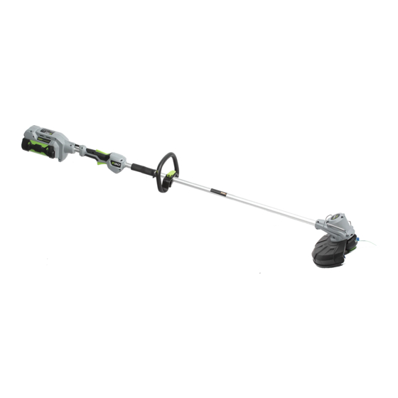
- Page 1 REPAIR GUIDELINE String Trimmer_ST1210E Version: 1 Issue Date: 2015/03/04...
-
Page 2: Table Of Contents
Table of Contents Contents Page Troubleshooting Tool list Part 1: Replace the motor 6-19 Part 2: Replace the carbon brushes 20-23 Part 3: Replace the PCBA 24-34... -
Page 3: Troubleshooting
Troubleshooting Fault Problem Possible Cause Test & Solution Position Replace the cutting line. (e.g. 2mm Not feed line Poor cutting line trimmer line round nylon line or 2mm Hitachi twist line) It’s overload of the motor. It usually caused by the too long line (user did Mount the guard on the string trimmer, Lose 50% of the RPM when not mount the guard when operating... - Page 4 Troubleshooting Fault Problem Possible Cause Test & Solution Position Motor was burned due to overload motor Replace the motor The motor speed varies up and down when the trimmer works. The carbon brushes were short Carbon brush Replace the carbon brushes.
-
Page 5: Tool List
Tool List For Repair Tool List SPEC Remark Magnetic bits #1 phillips Magnetic bits #2 phillips Socket wrench 13mm Electric soldering iron Heat gun Heat shrinkable sleeves Scissors To remove the shrinkable sleeve... -
Page 6: Part 1: Replace The Motor
Part 1: Replace the Motor... - Page 7 Replace the Motor 1. Remove the guard and bumper protector from the motor housing. bumper guard protector Description Part Number SPEC Guard Assembly 2824054000 Bumper protector 3650148000...
- Page 8 Replace the Motor Press the release tabs to remove the spool and spool retainer. Spool retainer Release tab spool Description Part Number Spool 3127635000 Spool retainer 2824019000...
- Page 9 Replace the Motor Hold the bump knob and pull it straight out, remove the bump knob, compression spring, washer from the trimmer head base. Trimmer head base PULL compression spring bump knob washer Description Part Number Bump knob 2824022000 compression spring 3660582000...
- Page 10 Replace the Motor Wear gloves and hold the trimmer head base with one hand, use a 13mm manual socket wrench to turn the hexagon nut counterclockwise to loosen and remove it. hexagon nut...
- Page 11 Replace the Motor 5. Hold the trimmer head base and pull it straight out from the motor shaft. Remove the flange from the base. Take out the plain washer from the motor shaft. Trimmer head Motor shaft base Pull Description Part Number Trimmer head 2824082000...
- Page 12 Replace the Motor Remove the 6 screws in motor housing and open the housings. Description Part Number SPEC Tapping screw 5610032000 Motor housings 2823769000...
- Page 13 Replace the Motor 7. Remove the two connectors from the connection plates on the motor by pulling them straight out. 8. Replace the motor if it was burned. Description Part Number DC Motor 2730222000...
- Page 14 Replace the Motor 9. Position the new motor into motor housing, the two connection plates towards outside. 10. Mount two connectors to the connection plates on the motor. Align the cables in the grooves. Connection plate Connection plate Black cable Red cable Align the red cable in the groove...
- Page 15 Replace the Motor 11. Close the housings and locked with 6 tapping screws. 12. Assemble the trimmer head to the motor shaft. a) Mount the plain washer onto the motor shaft. b) Position the flange into the trimmer head base. Plain Trimmer head Flange...
- Page 16 Replace the Motor Mount the trimmer head base together with the flange onto the motor shaft, lock the base with the hexagon nut. hexagon nut...
- Page 17 Replace the Motor d) Fix the washer into the trimmer head base. e) Align the ribs in the bump knob with the slots in the trimmer head base, fix the bump knob onto the base. Press the bump knob until it is fully slid in position and locked by the base. washer Align the ribs with slots in the base...
- Page 18 Replace the Motor Put the spool in the spool retainer and mount the spool retainer to the trimmer head base. Spool retainer spool...
- Page 19 Replace the Motor 13. Fix the guard and the bumper protector on the motor housing. 14. Test the motor.
-
Page 20: Part 2: Replace The Carbon Brushes
Part 2: Replace the Carbon Brushes... - Page 21 Replace the Carbon Brushes 1. Remove the screw and clamp plate which is used for locking the brush holder. Description Part Number Tapping Screw 5610011000 Plain Washer 5650001000...
- Page 22 Replace the Carbon Brushes 2. Use a flathead screwdriver to take out the spacer. 3. Lift up the outside of the brush holder and take out the carbon brush. 4. Replace with a new set carbon brush. Spacer Description Part Number Qty.
- Page 23 Replace the Carbon Brush 6. Insert new carbon brush into the brush holder, use a flathead screwdriver to pull the carbon brush onto the commutator of the motor. 7. Insert the spacer between the brush holder and motor housing bracket. 8.
-
Page 24: Part 3: Replace The Pcba
Part 3: Replace the PCBA... - Page 25 Replace the PCBA 1. Loosen the screws in the rear housing (8 pcs) and handle (6 pcs), open the housings. Description Part Number Qty. Tapping Screw 5610032000...
- Page 26 Replace the PCBA 2. Loosen the two locking screws, take out the lock-off trigger, switch trigger and connecting Tube from the housings. Description Part Number Qty. Fixed Ring 3705178000 Plain Washer 5650005000 Tapping Screw 5610032000...
- Page 27 Replace the PCBA 3. Replace the lock-off trigger or switch trigger if they are broken. Lock-off Trigger Compression spring Switch Trigger Description Part Number Qty. Lock-off Trigger 3127332000 Compression Spring 3660453000 Switch Trigger 3127331000...
- Page 28 Replace the PCBA 4. Remove the heat-shrinkable sleeves from the connectors with a scissors. 5. Move the transparent sleeve aside and pull the connectors to separate.
- Page 29 Replace the PCBA 6. Take out the PCBA from the housing. Description Part Number Qty. 7. Replace with a new PCBA. PCBA 2830069000 Battery release button 3127201000 8. The battery release button, latch, battery Latch 3127202000 ejection lever, housings can be replaced if Battery ejection lever 3127206000 they are broken or worn.
- Page 30 Replace the PCBA 9. Place new heat-shrinkable sleeve through the connectors. 10. Plug the two connectors and make sure they are fully insert in place. Correct connection: Red to White, Black to Black. 11. Move the heat-shrinkable sleeves to cover the connectors and use a hot air gun to shrink the sleeves. White Black Black...
- Page 31 Replace the PCBA 12. Position the connecting tube in the rear housing, lock it with the tapping screw. 13. Position the PCBA in the housing, align the cables in the grooves of housing. Cable alignment Cable alignment Fasten the screw...
- Page 32 Replace the PCBA 14. Fix the switch in the handle housing, align the cables in the grooves. Cable alignment Switch...
- Page 33 Replace the PCBA 15. Mount the switch trigger on the connecting tube and put the shaft and switch trigger into the handle housing. 16. Fix the lock-off trigger into the handle housing. Align the fixing hole in the trigger with Switch trigger the fixing pole on handle housing and push the trigger in place...
- Page 34 Replace the PCBA 17. Close the rear housing and handle housing. Locked the housings with 14 tapping screws.
Need help?
Do you have a question about the ST1210E and is the answer not in the manual?
Questions and answers