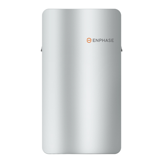
enphase EP200G101 Quick Install Manual

enphase EP200G101 Quick Install Manual

Hide thumbs Also See for EP200G101:

Advertisement

Quick Links

Q U I C K I N S T A L L G U I D E
Install the Enphase Enpower Smart Switch
To install the Enphase Enpower™ smart switch and the Enphase Enpower wall-mount bracket, read and follow all warnings and instructions in this guide and in
the Enphase Enpower Installation and Operation Manual at enphase.com/support. Safety warnings are listed on the back of this guide. These instructions are
not meant to be a complete explanation of how to design and install an energy storage system. All installations must comply with national and local electrical
codes and standards. Only qualified electricians shall install, troubleshoot, or replace the Enpower.
The Enphase Ensemble System includes the Enphase Enpower™ smart switch with Microgrid Interconnection Device (MID) capability, which
consolidates interconnection equipment into a single enclosure and streamlines grid-independent capabilities of PV and storage installations
by providing a consistent, pre-wired solution for residential applications. Along with MID functions, it includes PV, storage, and generator input
circuits.
For installing Enpower with 3rd party
PV inverter please refer to the planning
guide document on Enphase Energy
Storage System for third party PV
inverters online on Enphase website.
NOTE: The same installation scenarios
also apply to systems with legacy M-series
microinverters and Envoy-S Metered as
the communications gateway.
Whole home backup with Enpower
as service entrance and PV combiner
connected to Enpower. This is the preferred
configuration for back up of the entire main
load panel. This configuration supports up
to an 60A breaker for the PV circuit and an
60A breaker for battery storage.
Whole home backup with Enpower
as service entrance and PV combiner
connected to main load panel. This is the
preferred configuration when you back up
the entire main load panel, and the size of
the PV combiner circuit is more than 60A. In
this configuration, the PV combiner circuit
connection space in Enpower is left vacant.
When existing PV combiner circuits are
connected to the main load panel, and you
want to add battery storage to the system,
you can keep the PV combiner connected
to the main load panel and connect only the
battery storage system to Enpower.
Partial home backup with main load panel
as service entrance and PV combiner
connected to Enpower. When PV circuits
breaker size is less than 60A, this is the
preferred configuration for partial home
backup with subpanel.
Model number: EP200G101-M240US00
Scenario 1:
Scenario 2:
Scenario 3:
© 2021 Enphase Energy. All rights reserved. Enphase, the Enphase logo, Enpower smart switch, Encharge storage system, IQ Envoy, IQ combiner, IQ microinvert-
er, Installer Toolkit, Enlighten and other trademarks or service names are the trademarks of Enphase Energy, Inc. Data subject to change. Rev04-09-27-2021

Advertisement

Table of Contents
loading
Need help?

Need help?

Do you have a question about the EP200G101 and is the answer not in the manual?

Questions and answers

Summary of Contents for enphase EP200G101

  • Page 1 Install the Enphase Enpower Smart Switch To install the Enphase Enpower™ smart switch and the Enphase Enpower wall-mount bracket, read and follow all warnings and instructions in this guide and in the Enphase Enpower Installation and Operation Manual at enphase.com/support. Safety warnings are listed on the back of this guide. These instructions are not meant to be a complete explanation of how to design and install an energy storage system.
  • Page 2: Installation

    INSTALLATION A ) Inspect the packaging and the Enpower for damage. Do not install or Use the Enphase Installer Toolkit™ mobile app for iOS and Android devices. use the Enpower if it has been damaged in any way. It allows installers to configure the system while on site, eliminating the B ) Ensure that you have the following: need for a laptop and improving installation efficiency.
  • Page 3 You must follow all NEC and local electrical codes. Install breakers as needed for the AC grid, main load, Enphase IQ Com- biner, Enphase Encharge batteries, and generator. These breakers are not Unbox and mount the Enpower on the wall included and must be ordered separately.
  • Page 4 O ) Use the included stowed conductors, as labeled, to wire the circuit the unit. Breaker functional position are not interchangeable with one breaker(s) for the Encharge batteries, Enphase Combiner, and generator, another. The wires to be connected to each breaker are located beside as needed.
  • Page 5 Wire the field connections F ) Connect the AC wires of Enphase Combiner, Encharge batteries, and generator into the terminal lugs at the bottom of the Enpower load center on the left. DANGER! Risk of electric shock. Check that all circuits connecting to the WARNING: Do not connect the AC wires directly into the Enpower are de-energized before wiring.
  • Page 6 Configuring PCS In the Enphase Storage System A ) Check that you have the following items. You must use the listed CTs and Enphase IQ Envoy or the Envoy-S Metered with the Enpower and Encharge for Power Control System functionality.
  • Page 7 Set Up the Power Control System (continued) PCS CT installation within Enpower Consumption CTs The arrows must point IQ Envoy Terminal Block toward the load, away from the grid. CU, 75C, 14AWG MIN PD, B300 MEAS CAT III OVC II Production | Consumption OVC III Digital Input...
  • Page 8 NOTE: The MPU avoidance use case requires configuration using the For recommendations please refer the tech brief Enphase installer toolkit version v3.0.8 or higher and Envoy software https://support.enphase.com/s/article/Load-and-Solar-Circuit-Control-using-Enpower-Auxiliary-Contacts version 6.1.32 or higher. Steps for connecting auxiliary contact for shedding excess PV or load:...
  • Page 9 NO2 is used to shed excess PV. See our techni- cal brief, Load and Solar Circuit Control using Enpower Auxiliary Contacts https://support.enphase.com/s/article/Load-and-Solar-Circuit-Control-using-Enpower-Auxiliary-Contacts 3. Insert into I/O port on En- for detailed line diagram and other details.
  • Page 10: Generator Connections

    Generator Connections A generator can be integrated with the Enphase Storage system without the E ) Purchase and install a hold-down screw kit (SKU: EP200G-NA-HD-200A) to secure the Generator breaker. need for any external ATS. It supports both manual and auto-start genera- tors.
  • Page 11: Operation

    DANGER: Risk of electric shock. There are many potential sources of voltage. Check any Enphase Encharge battery, PV, or other generation source for voltage. B ) You must ensure that all electrical circuits external to Enpower are completed...
  • Page 12: Safety Instructions

    SAFETY IMPORTANT SAFETY INSTRUCTIONS. SAVE THESE INSTRUCTIONS. This guide contains important instructions that you must follow during installation and maintenance of the Enphase Enpower. Failing to follow any of these instructions may void the warranty (enphase.com/warranty). Safety Instructions, continued In Case of Fire or Other Emergency DANGER: Risk of electric shock.

This manual is also suitable for:

M240us00

Table of Contents