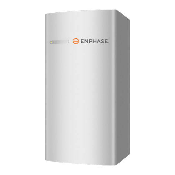
enphase Enpower EP200G101-M240US00 Quick Install Manual
Hide thumbs
Also See for Enpower EP200G101-M240US00:
- Quick install manual (7 pages) ,
- Technical brief (21 pages)
Advertisement
Q U I C K I N S T A L L G U I D E
Install the Enphase Enpower
To install the Enphase Enpower™ Smart Switch and the Enphase Enpower Wall-Mount Bracket, read and follow all warnings and instructions in this guide and
in the Enphase Enpower Installation and Operation Manual at enphase.com/support. Safety warnings are listed on the back of this guide. These instructions
are not meant to be a complete explanation of how to design and install an energy storage system. All installations must comply with national and local electri-
cal codes and standards. Only qualified electricians shall install, troubleshoot, or replace the Enpower.
The Enphase Ensemble System includes the Enphase Enpower™ Smart Switch with Microgrid Interconnection Device (MID) capability, which
consolidates interconnection equipment into a single enclosure and streamlines grid-independent capabilities of PV and storage installations
by providing a consistent, pre-
wired solution for residential
applications. Along with MID
functions, it includes PV,
storage, and generator (future)
input circuits.
Four unique installation scenari-
os are shown:
Whole home backup with Enpower
as service entrance and PV combiner
connected to Enpower. This is the
preferred configuration for back up
of the entire main load panel. This
configuration supports up to an 80A
breaker for the PV circuit and an 80A
breaker for battery storage.
Whole home backup with Enpower
as service entrance and PV combiner
connected to main load panel. This is
the preferred configuration when you
back up the entire main load panel, and
the size of the PV combiner circuit is
more than 80A. In this configuration, the
PV combiner circuit connection space
in Enpower is left vacant. When existing
PV combiner circuits are connected to
the main load panel, and you want to add
battery storage to the system, you can
keep the PV combiner connected to the
main load panel and connect only the
battery storage system to Enpower.
Partial home backup with main load
panel as service entrance and PV
combiner connected to Enpower.
When PV circuits breaker size is
less than 80A, this is the preferred
configuration for partial home backup
with sub-panel.
Model number: EP200G101-M240US00
Advertisement
Table of Contents

Summary of Contents for enphase Enpower EP200G101-M240US00
- Page 1 Install the Enphase Enpower To install the Enphase Enpower™ Smart Switch and the Enphase Enpower Wall-Mount Bracket, read and follow all warnings and instructions in this guide and in the Enphase Enpower Installation and Operation Manual at enphase.com/support. Safety warnings are listed on the back of this guide. These instructions are not meant to be a complete explanation of how to design and install an energy storage system.
-
Page 2: Installation
Enpower if it has been damaged in any way. Plan a location for the Enpower B ) Ensure that you have the following: One Enphase Enpower device. The Enpower shipping box contains an The Enpower housing is NEMA type 3R and can be installed indoors or •... -
Page 3: Install The Wall-Mount Bracket
Enpower device and affix it to the respec- tive location on a paper installation map. You will scan this map later using Enphase Installer Toolkit™ and your mobile device. You can find an example installation map at the back of any Enphase Microinverter manual. - Page 4 You can remove the door from the hinges if needed: Pinch the top of the Install breakers as needed for the AC grid, main load, Enphase IQ hinge rod using a pair of needle-nosed pliers. Slide the door up and away to Combiner, Enphase Encharge batteries, and generator (future).
- Page 5 F ) Use the included stowed conductors, as labeled, to wire the circuit breaker(s) for the Encharge batteries, Enphase Combiner, and generator (future), as needed. The stowed conductors are provided with crimped-on ferrules with end caps to prevent accidental contact.
-
Page 6: Operation
DANGER: Risk of electric shock. There are many potential sources of voltage. Check any Enphase Encharge battery, PV, or other generation source for voltage. B ) Yo must ensure that all electrical circuits external to Enpower are... -
Page 7: Safety Instructions
IMPORTANT SAFETY INSTRUCTIONS. SAVE THESE INSTRUCTIONS. This guide contains important instructions that you must follow during installation and maintenance of the Enphase Enpower. Failing to follow any of these instructions may void the warranty (enphase.com/warranty). In Case of Fire or Other Emergency...


Need help?
Do you have a question about the Enpower EP200G101-M240US00 and is the answer not in the manual?
Questions and answers