Advertisement
Quick Links
USER MANUAL
OZONE ANALYZER
Model UV-100
Overview
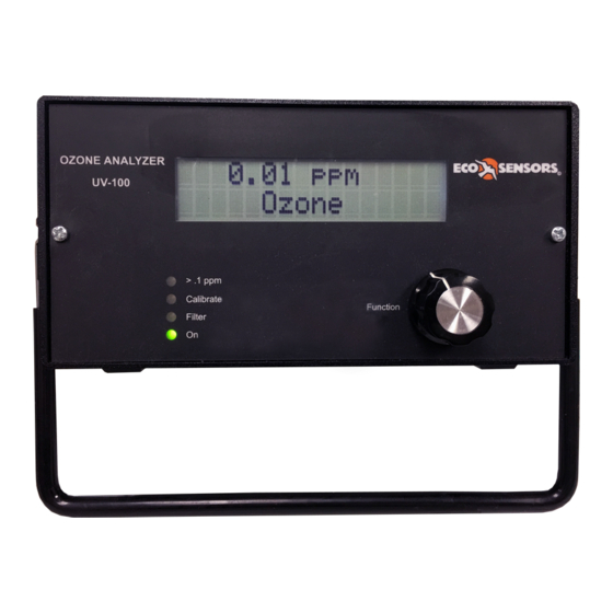
The model UV-100 is a UV absorption analyzer designed specifically for ozone. It uses a mercury lamp
filtered for absorption at 254 nm. The Eco Sensors design is compact and uses the latest digital
microprocessor technology. The standard calibrated range of the UV-100 is 0-999 PPM. Its outputs are
an LCD digital display, 0-2.5 VDC, 4-20 mA, and a time and date stamped digital data stream for
external readout and data logging. The data output are via serial port and USB. There is also an
internal data logger which can store and forward approximately 90 hours of data. The theory of
operation is described in Appendix D.
Panel LEDs indicate: power, low Lamp output, low pump flow rate, and ozone concentration at the
sampling point exceeds 0.1 PPM.
The instrument is conditionally warranted for one year. Read the warranty statement at the end of this
manual.
Operation
Plug the AC adapter into AC power and plug the adapter's output plug into the power jack on the
instrument. Find the power switch on the rear panel and turn the instrument on. The green LED
"Power" indicator and the LCD display backlighting should illuminate. Allow at least 30 minutes
warm-up. More than 1 hour is preferred if time permits. Initial PPM readings may start out high and
possibly drop to zero for a few minutes. Then the readings will tend towards the actual value as the
systems settles into equilibrium.
The compact, high-speed sample pump in the instrument makes a buzzing sound. This is
normal.
Connect your sample feed tubing to the instrument's 1/4" input compression fitting. The inlet tubing
should be made of PTFE (Teflon), PFA, FEP, PVDF or some other inert material that does not destroy
ozone and that does not desorb plasticizers and other organics that can contaminate the flow path. The
length of tubing should be kept as short as possible (preferably not more than a few feet) to minimize
ozone destruction within the inlet tubing. Tygon, polypropylene (which may look like Teflon) and metal
tubing should not be used. FEP-lined Tygon tubing, which is used inside the instrument provides the
flexibility of Tygon with the inertness of FEP. A Teflon or PVDF inlet filter is highly recommended to
prevent internal contamination of the tubing and absorption cell by particulate matter. Filters and filter
holders are available through Eco Sensors.
Eco Sensors
Ozone Analyzer, Model UV-100
1
Division of KWJ Engineering Inc.
User Manual, Rev. 2.0
sales@ecosensors.com or (800) 472-6626
Advertisement

Related Manuals for ECO Sensors UV-100


Summary of Contents for ECO Sensors UV-100
- Page 1 Model UV-100 Overview The model UV-100 is a UV absorption analyzer designed specifically for ozone. It uses a mercury lamp filtered for absorption at 254 nm. The Eco Sensors design is compact and uses the latest digital microprocessor technology. The standard calibrated range of the UV-100 is 0-999 PPM. Its outputs are an LCD digital display, 0-2.5 VDC, 4-20 mA, and a time and date stamped digital data stream for...
-
Page 2: Front Panel
Power Input RS-232 Serial Gas Sample Fitting ¼” nylon Swagelok 12-24 VDC Serial 2.5 VDC Output @ 400mA Output 4-20 mA Output Eco Sensors Ozone Analyzer, Model UV-100 Division of KWJ Engineering Inc. User Manual, Rev. 2.0 sales@ecosensors.com or (800) 472-6626... - Page 3 Low Lamp: UV Lamp output is below normal levels. This can be caused by internal contamination or a fault in the lamp or lamp circuitry. Contact our Technical Support if this light turns on. Power: UV-100 is powered and operating. Function Knob The Function Knob is used to navigate the instrument menu.
- Page 4 The options are represented in terms of averaging times. The minimum measurement cycle of the UV-100 is 10 s, therefore the default selection of 10 s represents no additional averaging. A 1 m average time will average 6 discrete measurements. A 5 m averaging time will average 30 discrete measurments.
- Page 5 Power Loss: The log data is retained when the UV-100 loses power or when it is turned off with the power switch. In these circumstances, when power is returned to the UV-100, the note: “Data Interruption” is written to the log file and then logging is resumed.
- Page 6 From the Cfg submenu, select Cal and push the Function Knob. The Cal submenu will appear: Cal Menu Fm O3 Eco Sensors Ozone Analyzer, Model UV-100 Division of KWJ Engineering Inc. User Manual, Rev. 2.0 sales@ecosensors.com or (800) 472-6626...
- Page 7 From the Cfg submenu, select I/O and push the Function Knob. The I/O submenu will appear: I/O Menu Bdr Ext Hrs Baud (Bdr): The baud rate is not adjustable at this time. Eco Sensors Ozone Analyzer, Model UV-100 Division of KWJ Engineering Inc. User Manual, Rev. 2.0 sales@ecosensors.com or (800) 472-6626...
- Page 8 External Outputs (Ext): The UV-100 includes analog voltage & current outputs as well as a relay that may be used to interface with other devices. Select Ext from the I/O submenu and push the Function Knob. The submenu will appear: Ext Menu REL1 REL2 V_OUT ...
- Page 9 Hours of Operation (Hrs): The UV-100 logs the total number of hours that it has been in use. This is helpful for determining when the instrument should be serviced. Select Hrs and push the Function Knob. The total number of hours will be displayed.
- Page 10 Technical Support. Digital Data Output The UV-100 may be connected to a computer (via USB or serial cable) to transmit real-time data or internally logged data. 3 -party terminal programs such as TeraTerm or puTTY are available online for interfacing with the UV-100.
- Page 11 Accessing the Serial Menu When the UV-100 is connected to a computer (via USB or serial cable), as described above, commands can be sent to adjust instrument parameters and initiate logging tasks. Listed below are the lower case command letters for performing operations while the instrument continues to measure.
- Page 12 Temperature LOW: 5 HIGH: 50 Pressure LOW: 500 HIGH: 1100 Flow LOW: 400 HIGH: 2000 Photodiode Voltage LOW: 0.6 HIGH: 2.45 Eco Sensors Ozone Analyzer, Model UV-100 Division of KWJ Engineering Inc. User Manual, Rev. 2.0 sales@ecosensors.com or (800) 472-6626...
- Page 13 Components with a limited lifetime are the air pump (~5,000 hours), lamp (~20,000 hours) and solenoid valve (rarely fails). It is recommended that the instrument be returned to Eco Sensors if any of these components fail. The following are indications of various instrument malfunctions.
- Page 14 AC Adapter The Eco Sensors P-20-15 adapter is included with every UV-100. This adapter is suitable for Type A power outlets (North America). Adapters for other locations may be available for special order from Eco Sensors. Otherwise, adapters should be purchased locally that fit local wall sockets and conform to local codes.
- Page 15 11-28 VDC, nominally 500 mA at 12 V, 6.0 watt Enclosure Size: 3.75 x 8.5 x 8.5 in (9.5 x 21.6 x 21.6 cm) Weight: 4.0 lb (1.8 kg) Eco Sensors Ozone Analyzer, Model UV-100 Division of KWJ Engineering Inc. User Manual, Rev. 2.0 sales@ecosensors.com or (800) 472-6626...
- Page 16 If a defect develops during the warranty period, Eco Sensors, in its sole discretion, will repair the instrument or replace it with a new or reconditioned model of equivalent quality. In the event of replacement with a new or reconditioned instrument, the replacement unit will continue the warranty of the original unit.
- Page 17 Using the Connection The UV-100 may be connected to a computer (via USB or serial cable) to transmit real-time data or internally logged data. 3 -party terminal programs such as TeraTerm or puTTY are available online for interfacing with the UV-100.
- Page 18 APPENDIX C Pinout of the DB-9 Connector Rear view of the UV-100 DB-9 Connector (Male) 1 2 3 4 5 ● ● ● ● ● ● ● ● ● 6 7 8 9 Pin Description: 0-2 V Analog Signal Out...
- Page 19 To destroy mold the space is held at a very high Ozone level for a predetermined amount of time. The generator is controlled using the set point relay on the back of the UV-100 to hold Ozone. After the Ozone “dwell” interval is complete, generator power is shut off or UV-100 generator ON level is set to zero.
- Page 20 UV-100. Several methods can used to shield the UV-100 from theses extremes. The UV-100 is kept isolated by being outside the cold space and by using a long length of inlet tubing, the majority of which coiled outside the cold space. This allows for the inlet sample to be warmed to an acceptable level before measurement.
- Page 21 APPENDIX E Theory of Operation The Eco Sensors Ozone Monitor is designed to enable accurate measurements of indoor ozone over a wide dynamic range extending from a limit of detection of .01 ppm by volume (ppmv) to an upper limit of about 1,000 ppm based on the well-established technique of absorption of ultraviolet light at 254 nm.
- Page 22 The major difference that will be observed from the lack of P and T compensation is at high altitudes the UV-100 will read a higher ozone concentration inversely proportional to the barometric pressure at the higher altitude versus the barometric pressure at sea level.
Need help?
Do you have a question about the UV-100 and is the answer not in the manual?
Questions and answers