Table of Contents
Advertisement
Advertisement
Table of Contents

Related Manuals for Boss SY-200


Summary of Contents for Boss SY-200
- Page 1 Owner’s Manual Before using this unit, carefully read “USING THE UNIT SAFELY” and “IMPORTANT NOTES” (leaflet “USING THE UNIT SAFELY” and Owner’s Manual (p. 17)). After reading, keep the document(s) where it will be available for immediate reference. © 2021 Roland Corporation...
-
Page 2: Top Panel
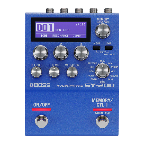
Panel Descriptions Top Panel Display Displays various information such as the current memory number. [MEMORY] knob MEMORY (turn the knob) Turn the knob to switch between memories 1–128 (p. 7). To change a value in larger steps, turn a knob while pressing it. -
Page 3: Menu Button
Panel Descriptions [MENU] button [E. LEVEL] knob The menu screen appears. This adjusts the volume of the effect sound (synth sound). [EXIT] button [VARIATION] knob Returns you to the previous screen. In some screens, this cancels the function currently being executed. This selects variations for the type that is selected. -
Page 4: Rear Panel
Panel Descriptions Rear Panel [ON/OFF] switch Turns the effect (synth sound) on/off. * To prevent malfunction and equipment failure, always turn down the volume, and turn off all the units before making any connections. [MEMORY/CTL 1] switch Switches between memories (p. 7). Holding this down makes it function as the [CTL 1] switch. -
Page 5: Output Jack
Panel Descriptions * Once everything is properly connected (p. 4), be sure to follow the CTL 2, 3/EXP jack procedure below to turn on their power. If you turn on equipment in the wrong order, you risk causing malfunction or equipment failure. Using the jack as CTL 2/3 * Before turning the unit on/off, always be sure to turn the volume down. -
Page 6: Side Panel
Panel Descriptions Side Panel MIDI jacks Use a TRS/MIDI connecting cable (BMIDI-5-35, sold separately) to connect an external MIDI device. You can use an external MIDI device to switch between memories on this unit. * Do not connect an audio device here. Doing so will cause malfunctions. - Page 7 Saving and Switching Between Memories Saving to a Memory Switching Between Memories You can save the settings you’ve edited. Here’s how to recall a saved memory. Press the [MENU] and [EXIT] buttons at the Turn the [MEMORY] knob. same time. The memory number changes in ascending order (1 0 2 0 3 0 4...
- Page 8 Saving and Switching Between Memories Exchanging Memories Initializing a Memory You can change the order of saved memories by You can return (initialize) a memory to its standard exchanging them. settings. This is useful when you want to create a new tone from scratch.
-
Page 9: Basic Operations
Various Settings (Menu) Assigning functions to an external pedal Basic Operations You can connect a footswitch (FS-5U, FS-6 or FS-7, sold separately) Press the [MENU] button. to the CTL 2, 3/EXP jack, and use it to tap-input the tempo or to switch memories. -
Page 10: Parameter List
Various Settings (Menu) Parameter List Parameter Value Sets how the switch operates. ON/OFF: ON/OFF FUNCTION TOGGLE: Switches the effect with each press of the switch. These parameters specify the function of the [ON/OFF] MOMENT: Switches the effect only while the switch is pressed. switch. - Page 11 Various Settings (Menu) Parameter Value Parameter Value Selects which function the switch controls, Sets how the switch operates. as follows. TOGGLE: Switches the effect with each MEMORY: Selects the memory. press of the switch. SW MODE S.HOLD: Holds (sustains) the sound. This MOMENT: Switches the effect only makes the sound you play sustain.
- Page 12 Various Settings (Menu) EXP PDL FUNCTION Here's how to set the multi settings. Set the minimum (MIN) value using the [1], [2], [3], [D. Specifies the function of the expression pedal connected LEVEL] and [E. LEVEL] knobs. to the CTL 2, 3/EXP jack. Press the [MEMORY] knob.
- Page 13 Various Settings (Menu) SYSTEM MIDI Parameter Value Parameter Value Switches to settings that are suitable for a Specifies the MIDI receive channel. guitar or a bass. MODE If this is “OFF, ” MIDI messages are not RX CH GUITAR, BASS received.
-
Page 14: Midi Pc Map
Use the program change map to customize which Specifies the controller number corresponding to each controller. ON/OFF SW CC memories on the SY-200 correspond to which program OFF, #1–31, #64–95 CTL1 CC change messages sent from an external MIDI device, CTL2 CC switching to the memory in question. -
Page 15: Restoring The Factory Settings
Insert the batteries facing the correct way, as shown in the illustration. Here’s how to restore the SY-200 to its factory defaults. You can also restore just the system settings or part of * Batteries should always be installed or replaced before connecting any other the memories. -
Page 16: Attaching The Rubber Feet
Appendix Attaching the Rubber Feet Main Specifications Power Supply You can attach the rubber feet (included) if necessary. Alkaline battery (AA, LR6) x 3, AC adaptor (sold separately) 101 (W) x 138 (D) x 63 (H) mm / 4 (W) x 5-7/16 (D) x 2-1/2 (H) Attach them in the locations shown in the illustration. -
Page 17: Using The Unit Safely/Important Notes
USING THE UNIT SAFELY/IMPORTANT NOTES CAUTION Repairs and Data • Before sending the unit away for repairs, be sure to write Keep small items out of the reach of children down the needed information. Although we will do our utmost to preserve the data stored in your unit when To prevent accidental ingestion of the parts we carry out repairs, in some cases, such as when the listed below, always keep them out of the reach... - Page 18 “License”); You may obtain a copy of the License at http://www.apache.org/licenses/LICENSE-2.0 • Roland and BOSS are either registered trademarks or trademarks of Roland Corporation in the United States and/or other countries. • Company names and product names appearing in this document are registered trademarks or trademarks of their respective owners.
Need help?
Do you have a question about the SY-200 and is the answer not in the manual?
Questions and answers