
Related Manuals for Marway Optima 833 Series


Summary of Contents for Marway Optima 833 Series
- Page 1 Optima 833 Series ™ Power Distribution Units Operating Guide and Reference Sep 2021 : P/N 501055-000 Rev B...
-
Page 2: Table Of Contents
General 1.1 Documentation Symbols (EN) ..........3 1.2 Safety Notices (EN) ..............3 1.3 Symboles de Documentation (FR) ........4 1.4 Avis de sécurité (FR) .............. 4 1.5 General Description ............... 5 1.6 Product Models ..............5 1.7 Product Ratings ..............6 Installation 2.1 Installation Notes .............. -
Page 3: General
The mains inlet plug shall be installed so that it is easily accessible. • This product is equipped with a safety ground connection through the mains inlet plug, as well as a redundant chassis ground screw on the rear panel. Ensure that the product is properly grounded before applying power. • Disconnect all power to the product prior to servicing control signal cabling. • Do not open this product as it contains no user serviceable parts inside. All service concerns should be directed to Marway Power Solutions. • I f this product is used in a manner which does not comply with this instruction manual, the protection provided by the equipment may be impaired. • All work on connections must be carried out under zero voltage (output disconnect), and may only be performed by qualified and informed persons. Improper actions can cause fatal injury as well as serious material damage. -
Page 4: Symboles De Documentation (Fr)
• C e produit est équipé d’une mise à la terre de sécurité via la prise d’alimentation secteur, ainsi que d’une vis redondante de mise à la terre du châssis. Assurez-vous que le produit est correctement mis à la terre avant de le mettre sous tension. • D ébranchez toute alimentation électrique du produit avant d’effectuer l’entretien du câblage des signaux de commande. • N ’ouvrez pas ce produit, car il ne contient aucune pièce réparable par l’utilisateur. Tous les problèmes de service doivent être adressés à Marway Power Solutions. • S i ce produit est utilisé d’une manière non conforme au présent manuel d’instructions, la protection fournie par l’équipement peut être compromise. • T ous les travaux sur les connexions doivent être effectués sous une tension nulle et ne doivent être effectués que par des techniciens qualifiés et compétents. Des actions inappropriées peuvent entraîner des blessures mortelles et des dommages matériels graves. • C e produit est conçu pour une utilisation à l’intérieur uniquement et ne doit pas être exposé à ... -
Page 5: General Description
5-20R duplex receptacle which is not controlled by the remote-EPO feature. There are two styles of outlet configurations. The first is where all outlets are 5-20R. These are separated into four circuits of four outlets. The second style includes three circuits of four 5-20R outlets, two circuits each with one L5 or L6 twist lock outlet, and one L21-20R outlet which is fed directly from the main breaker (there is no branch breaker). All models are constructed of a steel chassis, and designed for fixed mounting within a 3U rack space in an EIA-310 compliant rack enclosure. This documentation is about the hardware elements of the Optima 833 Series of PDUs. For detailed information about the software, you’ll need the Optima RCM User Guide : Software and Basic Controls Reference located on our website at http://www.marway.com/docs. Product Models Models are primarily organized by what type of power inlet they have. Then by the outlet configurations. All models have a continuous duty rating of 24 A per phase at the inlet (30 A maximum). All models have two unswitched 5-20R outlets in addition to the switched outlets noted in the table below. Inlet Configurations Switched Outlet Configurations Straight... -
Page 6: Product Ratings
Product Ratings All models of the 833 Series have the same input rating. Outlet ratings vary depending on the outlet type. Inlet Rating Outlet Ratings ɸ 120 Vac, 1 , 16 A continuous (20 A max.) per NEMA 5-20R duplex receptacle ɸ NEMA L21-30P 120 Vac, 1 , 16 A continuous (20 A max.) per NEMA L5-20R receptacle ɸ 120/208VAC 120 Vac, 1 , 24 A continuous (30 A max.) per NEMA L5-30R receptacle ɸ ɸ 4P5W 208 Vac, 1 , 16 A continuous (20 A max.) per NEMA L6-20R receptacle ɸ... -
Page 7: Installation
2 Installation Installation Notes The following guidance must be followed for proper installation of the product. 1. Mounting: This product is designed for mounting in an EIA-310 compliant 19” rack. The user is responsible for ensuring the mounting method provides adequate structural support for the product, and any attached cables. The user is also responsible for ensuring the mounting location provides adequate ventilation to dissipate heat generated during operation of the product. Ensure the product is securely mounted before applying power. 2. Chassis ground: The rear of the chassis includes a redundant chassis ground screw and ground wire. If desired for your installation location, connect the chassis ground wire to the rack cabinet using an appropriate fastener. 3. Optionally, connect the appropriate cables between the PDU outlets and the equipment being powered by the PDU. This may be done later according to the startup procedures suitable to the end-user’s equipment and application. 4. If applicable, connect the cabling between the PDU and remote EPO control panel. 5. PDU Main Breaker: Ensure the Main Breaker on the front of the PDU is in the off position before connecting the PDU’s inlet cable to the facility power source. (It is best to switch all breakers to the off position.) 6. Facility Power Source: The single-phase facility power source for this product must include an overcurrent protective device capacity as defined in the table below: Continuous Current Mains Protection Main Inlet Rating Required NEMA 5-15P 12 A 15 A NEMA 5-20P 16 A 20 A NEMA L5-20P... -
Page 8: Operation
3 Operation Controls Remote Override Breaker EPO Only Menu Ethernet Serial Aux 1 Aux 2 PRESS Rear Panel RESET Remote Devices Left Side Ethernet Serial Aux 1 Aux 2 Values Enable J 22 Disable Return Enable Disable J 20 J 21 Return J 23 Delay... -
Page 9: Startup To Configure The Software
6. Switch each branch breaker to the On position. The internal outlet control relays, and remote switching/EPO system are able to prevent power from reaching the outlets. However, with a factory default setup, power should now be applied to all outlets. I there is not an EPO panel connected to the PDU, leave the Remote Override switch to the up position. If there is a remote EPO panel connected to the PDU, such as Marway’s Commander UCP 5000, flip the switch to the down Remote position. This system is discussed in detail farther down, as well as in the Optima RCM User Guide : Software and Basic Controls Reference located on our website. The PDU can continue to be used in this way as long as needed. The software can be configured later, or can be left unconfigured if it will not be used. 3.1.2 Startup to Configure the Software The document Optima RCM User Guide : Software and Basic Controls Reference located on our website at http://www. -
Page 10: Branches
(CB 5) J 12 Choice of (CB 3) twist-lock J 17 3.3.3 Controls Breaker There is a small pop-out breaker protecting the control system components. This isn’t used during normal operation. If it were to pop out, try pressing it back in. If it fails to stay in, there may be failure in one of the controls which is shorted, or is drawing excessive current. This would likely indicate the need for an RMA repair. Contact Marway support. Page 10 Optima 820 Series... -
Page 11: Remote Switching / Epo Option
Remote Switching / EPO Option All model include Marway’s Remote Switching / EPO system. This includes the controls to interface to Marway’s optional Commander UCP 5000 Remote On/Off/EPO and similar compatible panels. This panel is not required to operate the PDU. Controls Remote Override Breaker EPO Only Menu Ethernet Serial Aux 1 Aux 2 PRESS RESET Remote Input Devices Ethernet Serial Aux 1 Aux 2 Values Enable Disable Return J 20 J 21 Optima RCM Main Breaker CB 1... -
Page 12: Remote Bus Connector
Outlet Control Bus Outlet Control Bus Enable Enable Enable Enable Disable Disable Return Return Return Return Marway Commander UCP 5000 Remote EPO J 22 J 22 (CB 1) (CB 1) J 14 J 13 J 14 J 13 Enable Enable Disable... -
Page 13: Digital Power Meter
Main Breaker CB 1 CB 2 CB 3 CB 4 CB 5 CB 7 The display will default to showing the amperage being drawn by each phase in the system (all outlets, plus the internal control system). It will update approximately every 3 seconds, rotating through the three phases one at a time. The keypad can be used to navigate through power values for volts, amps, watts, voltamps, voltamps reactive, power factor, and Hertz for each phase, as well as the on/off status of the software controlled outlet relay. (The outlet relay cannot be controlled from the keypad however.) For complete display and keypad details, refer to the document Optima RCM User Guide : Software and Basic Controls Reference located on our website at http://www.marway.com/docs. Obtain that document, and review the Display and Keypad Operation chapter. EMI Filter There are no control associated with the EMI filter. It is a passive device working at all times to reduce common mode and differential mode noise on the incoming power lines. Page 13 Optima 820 Series... -
Page 14: Reference
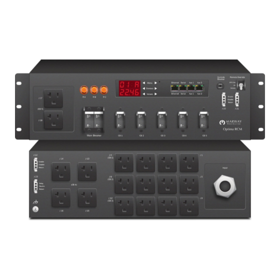
(1) Main 24/30 A breaker and phase-power indicators. recessed-chassis position. The brackets may also be removed for table top operation, or adaptation of (2) Branch 16/20 A circuit breakers for outlets. Some the end user’s own brackets. models have 5, some models have 6. (3) Ethernet, RS-232 serial console, and auxiliary connections. All are RJ-45. Auxiliary connectors are Optional Configurations for Marway Temperature/Humidity sensors. (4) Digital display of inlet power data and relay state. (6) Internal controls 1 A, push-type breaker. Included with inlet power option. (7) Remote EPO mode switch. A three-position toggle (5) Display navigation keypad. Included with inlet power provides manual control over the remote EPO mode. option. “3.4 Remote Switching / EPO Option” on page for a description. -
Page 15: Specifications
• All models include a thermally protected varistor on Main Breaker state. each phase with a single-pulse energy rating of 120 joules. Optima Remote EPO Circuit • All models have a peak surge current rating of Marway UCP, or Marway Optima PDU 10,000 A for a single pulse 8x20µs wave. customer supplied circuit Remote On EPO Override... - Page 16 © 2021, Marway Power Systems, Inc. All rights reserved. Optima™, Optima RCM™, Commander™, TwinPower™, mPower™, and mPower DC™ are trademarks of Marway Power Systems, Inc. All other trademarks are the property of their respective owners. Global Support Contacts Web: www.marway.com Email: support@marway.com...
Need help?
Do you have a question about the Optima 833 Series and is the answer not in the manual?
Questions and answers