
Related Manuals for Marway Optima 533 Series


Summary of Contents for Marway Optima 533 Series
- Page 1 Optima 533 Series ™ Power Distribution Units Operating Guide and Reference Apr 2021 : P/N 501035-000 Rev B...
-
Page 2: Table Of Contents
3.2.1 Main Breaker ..............7 3.2.2 Branch Breakers ............. 7 3.2.3 Controls Breaker ............. 8 3.3 EPO Controls ................8 3.3.1 Remote Mode Switch ............8 3.3.2 Remote Bus Connectors ..........9 Reference Specifications Page 2 Optima 533 Series... -
Page 3: General
• Disconnect all power to the product prior to servicing control signal cabling. • Do not open this product as it contains no user serviceable parts inside. All service concerns should be directed to Marway Power Solutions. • I f this product is used in a manner which does not comply with this instruction manual, the ... -
Page 4: General Description
533011 533002 533007 533012 533003 533008 533013 533004 533009 533014 * Each model has one of two “dash number” designators: • –000 = the remote EPO is a Normally Open (N.O.) type • –001 = the remote EPO is a Normally Closed (N.C.) type Page 4 Optima 533 Series... -
Page 5: Product Ratings
120/208VAC 120 Vac, 1 , 24 A continuous (30 A max.) per NEMA L5-30R receptacle ɸ ɸ 4P5W 208 Vac, 1 , 16 A continuous (20 A max.) per NEMA L6-20R receptacle ɸ 50/60Hz 208 Vac, 1 , 24 A continuous (30 A max.) per NEMA L6-30R receptacle ɸ 24 A continuous 120/208 Vac, 3 , 24 A continuous (30 A max.) per NEMA L21-30R receptacle 30 A maximum 24 A continuous (30 A max.) total per phase regardless of receptacle combination (Outlet combinations are for connection flexibility, not for increased current capacity.) Page 5 Optima 533 Series... -
Page 6: Installation
6. Facility Power Source: The three-phase facility power source for this product must include an overcurrent protective device with a maximum rating of 30 Amps. The Optima 533 is a heavy product. The flange mounting ears are designed to hold the PDU securely against the rack mounting rails, but are NOT designed to support the weight of the PDU vertically. The end user is responsible for ensuring the PDU’s weight is properly supported by the rack’s infrastructure (which may involve adding support rails). Page 6 Optima 533 Series... -
Page 7: Operation
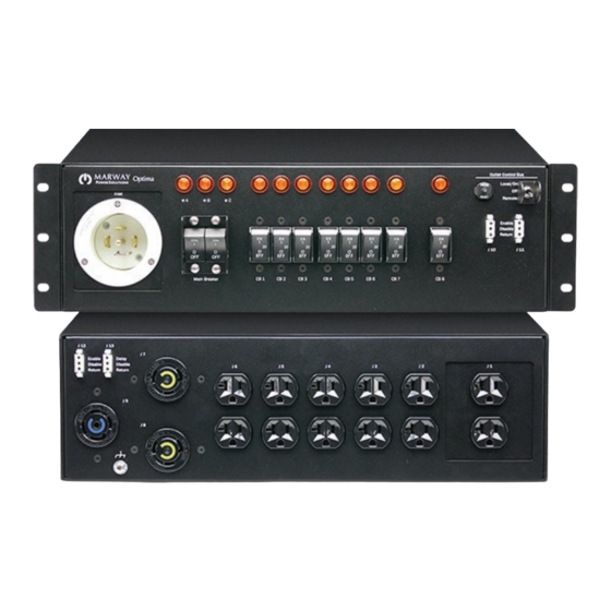
C indicators will be lit. All branch circuits are ready for use. As each branch breaker is switched on (e.g. CB1 , CB2 , etc.), the indicator above it will be lit. If there is not an EPO panel connected to the PDU, leave the switch in the up Local/On position. If there is remote EPO panel connected to the PDU, such as Marway’s Commander UCP 5000, flip the Outlet Control Bus switch to the down Remote position. 3.2 Breaker Controls The PDU has three distinct groups of controls: the main breaker, the branch breakers, and the remote EPO system. -
Page 8: Controls Breaker
There is a small pop-out breaker protecting the control system components. This isn’t used during normal operation. If it were to pop out, try pressing it back in. If it fails to stay in, there may be failure in one of the controls which is shorted, or is drawing excessive current. This would likely indicate the need for an RMA repair. Contact Marway support. 3.3 EPO Controls All Optima 533 PDUs include the controls to interface to Marway’s Commander UCP 5000 Remote On/Off/EPO panels ... -
Page 9: Remote Bus Connectors
Remote Bus connectors have two different numbering systems depending on the model. (Why? A convention from the military equipment realm is that all connectors are labeled sequentially. Since some models have 8 outlet junctions, and some have 9 outlet junctions, the subsequent connectors for the Remote Bus have labels of either J9, J10, J11, J12, or J10, J11, J12, J13.) Models with J1 through J8 Outlets The standard enable connectors are J9, J10, J11. These are all wired in parallel. The delay connector is J12. When used, the On signal from the remote panel is delayed by about 2 seconds. Models with J1 through J9 Outlets The standard enable connectors are J10, J11, J12. These are all wired in parallel. The delay connector is J13. When used, the On signal from the remote panel is delayed by about 2 seconds. Page 9 Optima 533 Series... - Page 10 Remote EPO Input Outlet Control Bus Outlet Control Bus Enable Enable Enable Enable Disable Disable Return Return Return Return Marway Commander UCP 5000 Remote EPO J 11 J 12 J 11 J 12 Enable Delay Enable Delay Disable Disable Disable Disable...
-
Page 11: Reference
Front panel remote EPO control bus interface. Two Power inlet. Some models include a recessed male connectors enable the PDU to be daisy chained connector as shown. Some models include a strain- between a remote EPO panel (such as Marway’s relieved 9-foot cable with an L21-30 plug. UCP) and another PDU, or between two PDUs. (10) All models include at least six 5-20R duplexes. -
Page 12: Specifications
• Operating Temperature: 32°F to 122°F Pin 2 : Disable Pin 3 : Return • Maximum Altitude: 6,562 feet Power Off, EPO Active • Relative Humidity: 5% to 85% non-condensing Enable Outlet Groups B & C Power On Page 12 Optima 533 Series... - Page 13 © 2021, Marway Power Systems, Inc. All rights reserved. Optima™, Optima RCM™, Commander™, TwinPower™, mPower™, and mPower DC™ are trademarks of Marway Power Systems, Inc. All other trademarks are the property of their respective owners. Global Support Contacts Web: www.marway.com Email: support@marway.com...
Need help?
Do you have a question about the Optima 533 Series and is the answer not in the manual?
Questions and answers