Table of Contents
Advertisement
Quick Links
Advertisement
Table of Contents

Related Manuals for Envent 131S


Summary of Contents for Envent 131S
- Page 1 Gas Chromatograph Models: 131S & 132S User’s Manual Revision 7.1 05 October 2021...
-
Page 3: Table Of Contents
Table of Contents Introduction ..........................1 About This Manual ........................1 Warranty and Liability Statements ..................1 1.2.1 Limitation of Warranty ....................1 1.2.2 Disclaimer ........................2 Safety Information ........................2 1.3.1 Key Symbols......................... 2 Equipment Overview ........................ 3 Theory of Operation ......................... 3 2.1.1 Important Definitions .................... -
Page 4: Introduction
Envent Engineering 131S and 132S Gas Chromatograph analyzer. This manual contains information essential to the safe and efficient operation of the 131S & 132S. This manual should be read by all personnel who will be installing, operating, or otherwise interacting with these models. -
Page 5: Disclaimer
An extended warranty may be available with certified start-up. Contact Envent Engineering Ltd for details. Envent Engineering Ltd reserves the right to change the product design and specifications at any time without prior notice. 1.2.2 Disclaimer No other warranty is expressed or implied. -
Page 6: Equipment Overview
A mixture containing one or more components which the analyzer will measure Thermal Conductivity Detector Thermal Conductivity A measurement of a material's ability to conduct heat Envent Engineering Ltd – 131S & 132S User’s Manual – Revision 7.1 Page 3... -
Page 7: Gas Chromatography
– this change causes the integrator to detect a millivolt difference and a peak is generated on the chromatogram. Envent Engineering Ltd – 131S & 132S User’s Manual – Revision 7.1 Page 4... -
Page 8: Chromatogram Output
(see Figure 2), where the peak’s relative size (height and width) is correlated to the concentration of the component in the sample. Figure 2. Labeled Diagram Depicting a Chromatogram Peak Envent Engineering Ltd – 131S & 132S User’s Manual – Revision 7.1 Page 5... -
Page 9: Computational Analysis
���� ���� ����=1 Where, Mole % Total un-normalized mole percent Number of components included in the total Mole % Individual mole percent concentration of component “n” Envent Engineering Ltd – 131S & 132S User’s Manual – Revision 7.1 Page 6... - Page 10 NMole % Normalized concentration (by mole percent) of component “n” Mole % Un-normalized concentration (by mole percent) of component “n” Mole % Total un-normalized mole percent Envent Engineering Ltd – 131S & 132S User’s Manual – Revision 7.1 Page 7...
-
Page 11: External Components & Dimensions/Clearances
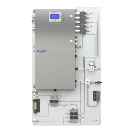
7. 1/2'' Myer hubs 8. 3/4'' NPT entries 9. External Ground Connection 10. Cable Gland 11. 1/2'' NPT entries Figure 3. Model 131S External Components & Dimensions/Clearances Inches [cm] Envent Engineering Ltd – 131S & 132S User’s Manual – Revision 7.1 Page 8... - Page 12 4. 1/2'' Myer hubs 5. Rigid Conduit Nipples 6. Solenoid Valves 7. External Ground Connection 8. Cable Gland Figure 4. Model 132S External Components & Dimensions/Clearances Inches [cm] Envent Engineering Ltd – 131S & 132S User’s Manual – Revision 7.1 Page 9...
-
Page 13: Technical Specifications
Three sensor inputs filtered with transient protection Analog Outputs Dual isolated 4-20 mA (2 wire standard, loop powered) Communications RS-232, RS- 485, TCP/IP Modbus Enron, Modicon 16, Modicon 32 Envent Engineering Ltd – 131S & 132S User’s Manual – Revision 7.1 Page 10... -
Page 14: Installation
3.2 Mounting Requirements The 131S is designed for cETLus Class 1, Division 1 (132S for Division 2), Groups BCD, Temp Code T3 (Tamb -20°C to +55°C). These models are designed for indoor use only. Ensure that the analyzer received is suitable for the electrical classification of the installation site. - Page 15 Conduit seals must be poured after wiring is completed and before powering up the unit. Refer to Appendix D for more information on the conduit sealing compound. Envent Engineering Ltd – 131S & 132S User’s Manual – Revision 7.1 Page 12...
-
Page 16: Electrical Connections
Relay Outputs on Mainboard (Relay 1 to 4) P7, are limited to 120VAC max, or used as dry contacts. The 4-20 mA output requires a 24 VDC power loop which can be supplied by the analyzer. Envent Engineering Ltd – 131S & 132S User’s Manual – Revision 7.1 Page 13... - Page 17 Figure 5. Electrical Customer Connections Envent Engineering Ltd – 131S & 132S User’s Manual – Revision 7.1 Page 14...
- Page 18 Figure 6. IS Ground Customer Connections Envent Engineering Ltd – 131S & 132S User’s Manual – Revision 7.1 Page 15...
-
Page 19: Operation
Wire power, analog outputs, discrete inputs & outputs, and communications to the GC Step 6. Check to ensure all bottles are securely fastened to wall mount brackets and Envent Engineering Ltd – 131S & 132S User’s Manual – Revision 7.1 Page 16... - Page 20 Connect serial cable to the GC from Laptop or a PC. Step 13. Load Envent ICE onto a laptop or PC. Step 14. Log onto the GC and validate communications. Envent Engineering Ltd – 131S & 132S User’s Manual – Revision 7.1 Page 17...
- Page 21 Deviation limits and that the calibration was noted as successful in the final calibration report. Step 21. Repeat steps 15-20 for each calibration table as required. Envent Engineering Ltd – 131S & 132S User’s Manual – Revision 7.1 Page 18...
- Page 22 Step 26. Save all device files and chart files to an appropriate location on the hard drive-in addition to factory calibration data for future reference. Envent Engineering Ltd – 131S & 132S User’s Manual – Revision 7.1 Page 19...
-
Page 23: Calibration Procedure
Operations > GC Control > Analysis Sequence and click the box for the calibration stream that requires calibration. Do not click the “continuous” check-box, only the gray button which surrounds the continuous check box. Envent Engineering Ltd – 131S & 132S User’s Manual – Revision 7.1 Page 20... - Page 24 A secondary purpose of calibration is to update the retention time for each component listed in the component table. The user can update RT based on analysis or calibration. This is configured in the component table shown below under RT Update. Envent Engineering Ltd – 131S & 132S User’s Manual – Revision 7.1 Page 21...
- Page 25 • Analyze cal. gas or additional reference gas as an unknown to compare with certified “as found” OR “as analyzed” results on the bottle • Contact Envent Engineering Ltd. if problems persist Envent Engineering Ltd – 131S & 132S User’s Manual – Revision 7.1 Page 22...
-
Page 26: Maintenance
The following maintenance procedures are required to validate proper GC operations and maintain performance: Step 1. During start up store and maintain all factory calibration reports and operational parameters shipped with the GC for future reference. Envent Engineering Ltd – 131S & 132S User’s Manual – Revision 7.1 Page 23... - Page 27 Note back flush peak relative to factory originals. • Save “ *.chart” files with chromatograms from valid calibrations and with comments at least once per year. Envent Engineering Ltd – 131S & 132S User’s Manual – Revision 7.1 Page 24...
-
Page 28: Monthly Check-Up
• It is recommended that a calibration is performed every 3 – 4 months. More frequent calibration may be necessary depending on operating conditions. Envent Engineering Ltd – 131S & 132S User’s Manual – Revision 7.1 Page 25... -
Page 29: Spare Parts And Consumables
Diaphragm Replacement Tool Tool kit required to work on, or replace, 400019 diaphragms for GC valves * NOTE: Contact Envent Engineering Ltd. to confirm that these part numbers are correct for the installed system 5.3 Filter Replacement Procedure Step 1. - Page 30 Step 17. Disable the field site bypass. • All connections must be leak tight to ensure the safety of the user and the functionality of the analyzer. Envent Engineering Ltd – 131S & 132S User’s Manual – Revision 7.1 Page 27...
-
Page 31: Sample Conditioning System Cleaning Procedure
It is recommended to take pictures before disassembling the components of the sample conditioning system as this will aid in reassembly. Alternatively, refer to the provided customer drawing package Envent Engineering Ltd – 131S & 132S User’s Manual – Revision 7.1 Page 28... - Page 32 Refer to Section 5.3 for more detailed instructions when installing the new microfiber coalescing filter element into the filter housing. Step 10. Recalibrate the analyzer. Refer to Section 4.2 for the calibration procedure. Envent Engineering Ltd – 131S & 132S User’s Manual – Revision 7.1 Page 29...
-
Page 33: Troubleshooting
AO output has specified range. been modified Pressure gauge not Pressure gauge has A replacement pressure gauge is required. working been over pressurized Contact Envent Engineering Ltd. Envent Engineering Ltd – 131S & 132S User’s Manual – Revision 7.1 Page 30... - Page 34 Envent Engineering Ltd – 131S & 132S User’s Manual – Revision 7.1 Page 31...
-
Page 35: Appendix A - Risk Assessment
For atmospheres where there is H2S, depending on the levels and company policy, the operator must wear the appropriate equipment before servicing a Gas Chromatograph analyzer Envent Engineering Ltd – 131S & 132S User’s Manual – Revision 7.1 Page 32... - Page 36 Very Unlikely – Analyzer weight Operator(s) Body Injury Moderate (Low) Moderate (Low) In some cases, unpacking and transporting the analyzer will require a minimum of two persons. Envent Engineering Ltd – 131S & 132S User’s Manual – Revision 7.1 Page 33...
- Page 37 Health Effects of Hydrogen Sulfide (H S) at Varying concentrations Possible Health Effects Concentration No known health effects <1ppm Can be smelled Envent Engineering Ltd – 131S & 132S User’s Manual – Revision 7.1 Page 34...
- Page 38 Permanent brain damage and death in a few minutes even if removed to fresh air at once *Check local legislations as these values may vary between locations Envent Engineering Ltd – 131S & 132S User’s Manual – Revision 7.1 Page 35...
-
Page 39: Appendix B - Certifications
Appendix B – Certifications Go to the Envent website www.enventengineering.com to see the latest certificates for the 131S and 132S. Envent Engineering Ltd – 131S & 132S User’s Manual – Revision 7.1 Page 36... -
Page 40: Appendix C - Sealing Compound Information
Appendix C – Sealing Compound Information Envent Engineering Ltd – 131S & 132S User’s Manual – Revision 7.1 Page 37... - Page 41 Envent Engineering Ltd – 131S & 132S User’s Manual – Revision 7.1 Page 38...
- Page 42 Envent Engineering Ltd – 131S & 132S User’s Manual – Revision 7.1 Page 39...
- Page 43 Envent Engineering Ltd – 131S & 132S User’s Manual – Revision 7.1 Page 40...
-
Page 44: Contact Us
Toll Free: 1 (877) 936 – 8368 Tel: 1 (713) 567 – 4421 Tel: 86 (138) 0119 – 1148 Tel: (403) 253-4012 Fax: (403) 253 -4016 Email: info@enventengineering.com Envent Engineering Ltd – 131S & 132S User’s Manual – Revision 7.1 Page 41...
Need help?
Do you have a question about the 131S and is the answer not in the manual?
Questions and answers