Table of Contents
Advertisement
Quick Links
Advertisement
Table of Contents

Related Manuals for Fraser XIFOS 33


Summary of Contents for Fraser XIFOS 33
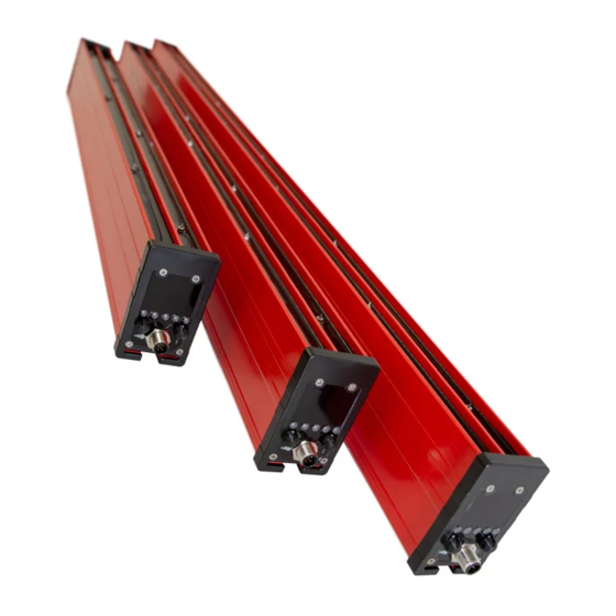
- Page 1 OPERATING INSTRUCTIONS XIFOS 33 WITH INTEGRATED REMOTE MONITOR...
-
Page 3: Table Of Contents
Contents Fraser static control equipment has been designed to give you many years of productive service. However, the science of static control has unique rules, which must be followed to allow the equipment to give a good return on your investment. Please read the following operating and maintenance instructions carefully. Contents Page Introduction . . . . . . . . . . . . . . . . . . . . . . . . . . . . . . . . . . . . . . . . . . . . . 4 Safety . -
Page 4: Introduction
The XIFOS 33 bar is one of the range of high performance DC static eliminators from Fraser Anti-Static Techniques. These products are used by leading manufacturers throughout the world to increase safety and productivity. It is essential that you read and understand the complete manual before installing and using this equipment. This is important for safety and for warranty cover. Features and Benefits The Fraser XIFOS 33 is a high-performance bar designed for long-range neutralisation of electrostatically charged surfaces. Powered by 24 V DC, it features integrated high voltage supplies meaning that no high voltage cabling is required. Distance Control: distance-to-target setting. See Section 7 . The status of the bar, including the need for cleaning, is indicated by 5 bi-colour LEDs on the endcap of the bar. Duplicate outputs enable integration with a control system or PLC. See Section 6. Intelligence Control: Intelligence ON/OFF. See Section 7 . The 24 V DC power supply and remote monitoring connections are made via an M12 5-pin connector. An external AC-DC PSU can be ordered if 24 V DC is not available. Mounting onto the machine is with ‘T’ fixings that slide into the slot in the bar. © Fraser Anti-Static Techniques Ltd 2020... - Page 5 Explanation of Symbols Warning! This symbol appearing in the operating instructions refers to operations which, if carried out improperly, can result in serious personal injuries. Caution! This symbol appearing in the operating instructions refers to operations which, if carried out improperly, can result in damage to property. Information! This symbol refers to information that relates to obtaining the best performance and operating life from the product. Checking on Delivered Equipment The equipment leaves our factory in suitable protective packaging. Please check that it is undamaged when it arrives. If there is visible damage, contact the Factory or one of our Distributors before carrying out any installation. Check that the parts which have been delivered are the same as you have ordered. Loose Parts Bars up to 1,000 mm in length are supplied with two ‘T’ fixings. Extra ‘T’ fixings are supplied for each additional 500 mm or part thereof. For example: 750 mm: 2 ‘T’ fixings 1,500 mm: 3 ‘T’ fixings 1,750 mm: 4 ‘T’ fixings It is important to use all of the supplied ‘T’ fixings. Emitter Key and two spare emitters. Power Supply Cable. M12 5-pin Connector and lead or Power Supply Unit - as per order. See Section 14 for details of cables and other accessories. Warning! DO NOT USE standard ‘computer style’ PSUs. These do not have secondary earth connections and risk shocks to the operator and damage to the bar. Only use the Fraser external Power Supply Unit (Part No. NEOS-PSU). XIFOS 33 OI - Iss.3 - EN...
-
Page 6: Safety
• As with all pulsed DC static eliminators, it is possible for the user to receive a small static shock as a result of their body being charged by the bar, and then discharging to a nearby earthed object. This is not dangerous, but may be uncomfortable and cause surprise. • The emitter pins of the bar are necessarily sharp. The emitter pins are a Class 2 mechanical energy source, as defined in EN 62368 -1:2014. Contact with them may be painful, but will not cause an injury requiring emergency medical attention. Take care when handling the bar. • Installation and maintenance work on the bar must only be carried out by suitably qualified personnel. • The negative pole of the 24 V DC supply provided to the bar must be permanently earthed. • Adequate installation earth/ground is required to ensure safe and proper operation . • Do not connect or disconnect the M12 cable from the bar while it is powered. • A small amount of ozone will be produced as part of the ionisation process. When installed correctly the level of concentration of ozone is less than 0.1 ppm and is within internationally accepted limits. • Any changes to the equipment without written consent of the manufacturer will nullify the warranty and certifications. • The bar is intended for use in indoor factory environments only. It is not suitable for outdoor use. © Fraser Anti-Static Techniques Ltd 2020... -
Page 7: Positioning Of The Bar
Positioning of the Bar The best location is at, or immediately before, the area where static is causing the problem. Remember that static can be regenerated if the material passes over rollers or through a process after neutralising. A Static Meter such as the Fraser 715 is useful to determine the best position. Important: Except on a winding reel of material (see the examples on the following page), the material to be neutralised must be in free air, not touching another surface as it passes the bar. It is not possible to neutralise static electricity where the material is touching another surface or roller. Incorrect location Static neutralisation will be very poor if there is not free air opposite the bar. MATERIAL û Good location Free air opposite the bar allows good neutralisation. MATERIAL FREE AIR ü XIFOS 33 OI - Iss.3 - EN... - Page 8 Positioning of the Bar Generally, with a rewind or unwind, it is desirable to use a long-range bar to cope with the changing geometry so that you can neutralise the reel from the core to the finished diameter at the end of the wind. There is an optimum location to neutralise the reel, which is shown by the following diagrams. The principle is to neutralise the film AFTER it leaves the final roller and as it joins the reel. Lay-on or Contact Roller Example If there is a lay-on or contact roller (C), the best position for the XIFOS 33 is on the side where the film leaves the lay-on roller - in this case the underside (A) - because it can neutralise the charge as soon as it is created. If this is not practical, then position the bar on the top side. (B) © Fraser Anti-Static Techniques Ltd 2020...
- Page 9 Positioning of the Bar Centre Winder Example On a centre winder the XIFOS 33 may be positioned above or below the reel. It is a good idea for the ionisation to be directed mainly at the reel, but also catching the single sheet, as shown at (A). Position (B) is also acceptable. It is often not possible to place a bar in the optimum position (A). The reason for this may be that the ideal bar location would get in the way of the loading/unloading process for the reels or would be in a position where operators might stand on it. In a dirty or dusty environment, it is better to place the bar facing down, since the face of the bar will not be covered by the dust. This is not a problem. It is possible to position the bar at other positions, such as (B) and still achieve a very good result. We always say that a film web must be in ‘free air’ and not touching a roller to achieve good neutralisation. This is because we know that the charge on the material will temporarily combine with the roller and not be available for removal by the eliminator. This remains true. However, once you have a number of layers on a reel or winder, all with the same polarity of charge on them, the charge can no longer combine and can therefore be neutralised layer by layer. XIFOS 33 OI - Iss.3 - EN...
-
Page 10: Installation
Installation Note: Long bars need careful handling during installation to avoid damage. Bars longer than 2,000 mm must be handled by two people. • Use all of the ‘T’ fixings provided for mounting the bar. The ‘T’ fixings slide into the slot in the base of the bar. When mounting the bar, the ‘T’ fixings must be evenly distributed along the length of the bar. Do not allow more than 800 mm of unsupported bar between ‘T’ fixings. • The bar must be dry and oil-free. • Only mount the bar with the slot touching the machine or the mounting bracket. • When mounting to the machine or on a bracket, make sure no metal extends beyond the slot in the bar. See the diagram below. Correct mounting Incorrect mounting bracket position bracket position û ü • It is important that the emitter pins are not touching, or close to metal objects, to avoid spark erosion that will damage both the bar and the metal object. • The distance from the material should be: 250 - 1,500+ mm. Area to be free of all ground references © Fraser Anti-Static Techniques Ltd 2020... -
Page 11: Electrical Connections
The 0 V (negative) output of the 24 V DC supply to the bar must be earthed. If this is not done, the bar and the power supply will be damaged and all warranties will be voided. Electrical connections to the bar are made via the M12 5-pole male connector on the endcap of the bar. If using the Fraser Anti-Static external Power Supply Unit (Part No. NEOS-PSU), connect the M12 cable from the Power Supply Unit to the bar and ensure that the supplementary ground wire is connected to the installation protective earth before connecting mains power. If using a separate 24 V Power Supply and Cable (e.g. as part of a machine control cabinet installation), follow the instructions in Section 5.2 for connecting the bar. - Page 12 Electrical Connections M12 Pin Assignments The M12 connector pin numbering scheme is shown below. Pin 3 Male plug on Female socket on the bar the cable end Pin 2 Pin 1 Pin 5 Pin 4 The pin assignment and typical wire colours are given in the table below. The table refers to cables supplied by Fraser. Other cables can have different colour schemes. Colour Function Brown 24 V White Blue 0 V and Earth Black Status Grey or Green/Yellow Disable © Fraser Anti-Static Techniques Ltd 2020...
- Page 13 Electrical Connections Power Supply Connections The diagram below shows the power supply connection requirements. Fuse +24 V 2.5 A To the bar 0 V The 24 V supply connection (Pin 1, brown wire) must be fitted with a 2.5 A fuse. It is recommended that a type ‘T’ or ‘gG’ fuse is used. The 0 V supply connection must be connected to the installation protective earth (PE). This connection should be made at the power supply output terminal if possible. There is no additional grounding connection to the bar – it is essential that this connection is made externally. Warning! If the 0 V output of the DC power supply is not grounded, there is a risk that the operator can receive an electric shock from the M12 connector on the bar. Caution! If the 0 V output of the DC power supply is not grounded, damage can occur to the power supply and/or the bar. Caution! If the 0 V output of the DC power supply is not grounded the residual voltage (balance) level of the bar cannot be guaranteed. XIFOS 33 OI - Iss.3 - EN...
-
Page 14: Status Leds
All solid red There is a fault with the bar Inactive All flashing green/red ‘Clean Me’ . The bar needs attention. Active All flashing green Frequency of the HV. Bar OK. Active + Intelligence. Scrolling right, green Active The speed is proportional to the level of intelligence. - Intelligence. Scrolling left, green Active The speed is proportional to the level of intelligence. The bar is equipped with a remote monitoring interface that allows the operating status of the bar to be fed into a PLC system or checked remotely. See Section 11 for wiring instructions and examples for the remote monitoring interface . © Fraser Anti-Static Techniques Ltd 2020... -
Page 15: Operation And Control
Operation and Control The Distance Control Distance Control Distance Setting Use the Distance Control rotary switch to adjust the setting for the required distance to the target. The Distance Control alters the frequency of the duty cycle: • High frequency is best for short range • Low frequency is best for long range Control Neutralisation Distance Frequency Position 250 mm - 500 mm 5 Hz 350 mm - 750 mm 2.5 Hz 500 mm - 1,000 mm 1 Hz 750 mm - 1,500+ mm 0.5 Hz Warning! Turn off the bar when changing the setting. XIFOS 33 OI - Iss.3 - EN... - Page 16 Operation and Control The Intelligence Control Intelligence Control Intelligence Setting Use the Intelligence Control rotary switch to select Manual or Intelligent operation. In Manual mode, the bar produces ionisation purely determined by the setting of the Distance Control rotary switch. In Intelligent mode, the bar continuously assesses the state of the charge on the web and modifies the operating parameters of the bar to give optimal ionisation under all conditions. It adjusts the polarity, duty cycle and frequency of the ion emission to suit the application. The Intelligence setting can double the neutralisation power of a XIFOS 33 bar in Manual mode. XIFOS 33 Intelligence monitors the charge in the target and adjusts the ion emission to achieve faster neutralisation. There are practical limits to the sensing capability of the XIFOS 33 - if the electric field is weak or at a long distance it will be more difficult to monitor. Control Intelligence Function Position The bar operates in Manual mode. The bar operates in Intelligent mode. Warning! Turn off the bar when changing the setting. © Fraser Anti-Static Techniques Ltd 2020...
- Page 17 Operation and Control Selecting the Best Setting The factory settings for the XIFOS 33 are Intelligence ON and Distance Control position 2. This gives intelligent operation at medium distances. This setting can be changed to meet the actual requirements of the installation. Typical reasons for this could be: 1. Distance The XIFOS 33 intelligence loses sensitivity with distance, especially if the static charge level is not high. The Distance settings correspond to the distance to the object to be neutralised. See the distance chart for guidance. 2. Installation If there are metal parts in the target area or close to the XIFOS 33 bar, these could interfere with the sensing - giving it misleading information. See Installation in Section 4. 3. Intermittent Static Charge For example, if the target is not continuously present there is no charge to sense. In this case it can be better to turn off Intelligence and just use a Distance setting. 4. Speed of Process Faster material speeds benefit from closer distances and higher frequencies. A small amount of experimentation can be needed to produce the best performance for the application. Use the rotary switch controls on the endcap to change the settings. Warning! Turn off the bar when changing the setting. See the chart below for the typical range of each Distance setting. Distance Setting on the bar 250 - 500 mm 350 - 750 mm...
-
Page 18: Commissioning
Always disconnect the power before working on the bar. • Cleaning is the only maintenance required. Dirt around the emitters will reduce ionisation effectiveness and result in unsatisfactory static neutralisation performance . • The frequency of cleaning will depend on the process and the environment in which the bar is installed. The bar should be cleaned when ‘Clean Me’ is indicated by the endcap LEDs and/or the remote monitoring interface. • Our Fraser cleaning kit (Part No. 81220) is ideal for use, alternatively a toothbrush or nail brush can be used. Do not use a wire brush as this could damage the bar. • The bar can be washed with soapy water or Isopropyl alcohol (IPA), but it must be dry around the emitters before turning the power on. • Please note, when handling and cleaning, that the emitter pins are sharp and care is needed! • The emitter pins are shockless - there is a large resistor below each emitter reducing the current to a shockless level. However please note that DC current can transfer charge to a body if it is touching or close to an emitter for a longer period. This could give a shock when discharging. • The emitters on the XIFOS 33 bar should be replaced every two years or when worn. Please use the emitter key supplied with the bar to remove/replace. © Fraser Anti-Static Techniques Ltd 2020... -
Page 19: Troubleshooting
10. Troubleshooting In the event of problems with the bar, please use the following checks. Symptom Cause(s) Solution(s) Green LEDs: solid, The bar is operating correctly • See Section 6 for further information flashing or scrolling No lit LEDs Bar not powered • Check the power supply and connections • Check the fuse • Check the supply cable for damage Flashing red LEDs Standby mode . • Reduce the voltage at the DISABLE input to less than 12 V to restore the The DISABLE signal is active normal operation of the bar (18 - 28 V) Solid red LEDs Power supply voltage outside • Check and adjust the power supply voltage of specified range • Make sure that a correct power supply cable is used • Ensure the power supply is not overloaded HV supplies overloaded... -
Page 20: Remote Interface And Wiring Examples
11. Remote Interface and Wiring Examples This section describes the functioning of the remote monitoring interface in more detail and provides wiring examples for common installation types. 11.1 Signalling The XIFOS 33 bar features two PLC Type 1, 2 and 3 compatible outputs to enable remote monitoring of the bar status, and a DISABLE input to allow the HV supplies to be externally disabled when not required (‘Standby’ mode). For example, the bar can be linked into the safety interlock system of the machine to ensure operator safety during changeover periods. See wiring diagram and examples below. BROWN = +24 V DC WHITE = OK BLACK = STATUS GREY or GREEN/YELLOW = DISABLE BLUE = 0 V/GROUND XIFOS 33 INTERNAL M12 CONNECTOR BROWN = +24 V DC BLACK = STATUS WHITE = OK GREY = DISABLE BLUE = 0 V/GROUND © Fraser Anti-Static Techniques Ltd 2020... - Page 21 11. Remote Interface and Wiring Examples Remote Monitor outputs (OK, Status) Both outputs are compatible with IEC 61131-2 Type 1, Type 2 and Type 3 PLC inputs, capable of sinking or sourcing 50 mA continuously. The outputs can also be used for direct driving of external lamps or relays. See wiring diagram and examples in the next section. The remote monitor signals are valid 5 seconds after power is applied, according to the following conditions: Status Condition Ionisation (White, Pin 2) (Black, Pin 4) Bar powered, all OK Active (HV ON) HIGH HIGH Bar powered, requires attention Active (HV ON) HIGH (e.g. cleaning) Overload, hardware INActive fault or standby (HV OFF) mode . INActive Standby mode HIGH...
- Page 22 11. Remote Interface and Wiring Examples 11.2 Example Applications External relay An external relay can be connected for additional control/feedback applications. Coil rating 24 V, 1.2 W max. BLACK WIRE/STATUS WHITE WIRE/OK RELAY 24 V RELAY 24 V BLUE WIRE/0V & GROUND MAX 50 mA External PLC Input Type 1, Type 2 or Type 3 Interfacing to an external 24V IEC 61131-2 Type 1, Type 2 or Type 3 PLC digital input can be achieved by direct connection. STATUS BLACK WIRE WHITE WIRE MAX 50 mA © Fraser Anti-Static Techniques Ltd 2020...
- Page 23 11. Remote Interface and Wiring Examples 11.3 Remote DISABLE input The XIFOS 33 bar features a remote DISABLE input signal (Grey or Green/ Yellow wire). This may be useful for installations in which the bar is not used continuously and it is desirable that the bar should be inactive when not required, or in installations in which the operation of the bar is to be interlocked with other machinery. The HV supplies may be externally disabled (Standby mode) by applying any DC voltage between 18 V and 28 V to the DISABLE input, for example by using an external switch or relay contact between the DISABLE input and 24 V. Subsequently reducing the voltage at the DISABLE input to less than 12 V restores normal operation of the bar. BROWN WIRE +24 V SWITCH CLOSED - BAR IN STANDBY MODE SWITCH OPEN - NORMAL OPERATION GREY OR GREEN/YELLOW WIRE In Standby mode the internal HV supplies of the bar are disabled, the status LEDs flash red, and the OK output is inactive (open circuit) to indicate that ionisation is disabled. The DISABLE signal has a weak internal pull-down resistor, thus if the DISABLE signal is left disconnected the bar will operate normally. Caution! Voltage applied to the DISABLE input must not exceed 28 V DC, and must be of the correct positive polarity. The bar may be permanently damaged by connecting the DISABLE input to any voltage outside the range of 0 V - 28 V DC. Warning! Where the optional NEOS-PSU has been ordered ensure the Power Unit is connected to a 3-wire AC mains supply, Live + Neutral + Ground, and that the extra Earth wire from the power supply is bonded to Ground. With this optional supply an interface cable is required to access the remote monitor feature.
-
Page 24: Specification And Dimensions
0 V / 24 V output Sourcing (+24 V): 50 mA Output current Sinking (0 V): 50 mA Limited to 50 mA max. Compatibility Compatible with IEC 61131-2 Type 1, 2 and 3 PLC inputs Remote monitor states Bar OK, ‘Clean Me’ , Fault, Standby, Bar not powered Protection Under-voltage/over-voltage lockout, surge protection, reverse supply polarity protection. Internal protection Over-temperature protection. HV supplies protected against overload. Signalling outputs protected against short-circuiting. Environmental Conditions Ambient temperature 0 - 55 °C Relative humidity Maximum 70 %, non-condensing IP64. Bar will not be damaged by exposure to water, but will not Ingress protection function correctly if the emitters are bridged by moisture. © Fraser Anti-Static Techniques Ltd 2020... -
Page 25: Certification And Ce Declaration Of Conformity
12. Specification and Dimensions Mechanical Dimensions 52.8 x 93 mm (W x H) Length Minimum length 600 mm then 750 mm to 6,000 mm in 250 mm steps Mass 1.02 kg + (2.5 kg/m) e.g. 1,000 mm bar: 3.52 kg Materials FR-ABS, epoxy resin, tungsten emitters, steel fixings. Approvals CE Marking CE. CB and UL pending. EU LVD (2014/35/EU) EN 62368-1:2014 EU EMCD (2014/30/EU) Emissions: EN 61000-6-3:2007 Immunity: EN 61000-6-2:2005 ORDER LENGTH OVERALL LENGTH = ACTIVE LENGTH * note - overall length = order length + 7 mm (including end caps) ALL DIMENSIONS IN MILLIMETRES 13. Certification and CE Declaration of Conformity We declare that this equipment conforms to the following EU Directives: Low Voltage Directive: 2014/35/EU EMC Directive: 2014/30/EU... -
Page 26: Spare Parts And Accessories
14. Spare Parts and Accessories Item Picture Description Part No. 3 m cable. M12 female, bare ends. 81193 Straight socket. 5 m cable. M12 female, bare ends. 81194 Straight socket. 7.5 m cable. M12 female, bare ends. 81195 Straight socket. 10 m cable. M12 female, bare ends. 81196 Straight socket. 3 m cable. M12 female, bare ends. 81199 90º socket. 5 m cable. M12 female, bare ends. 81200 90º socket. 7.5 m cable. M12 female, bare ends. 81201 90º socket. 10 m cable. M12 female, bare ends. 81202 90º socket. © Fraser Anti-Static Techniques Ltd 2020... - Page 27 14. Spare Parts and Accessories Item Picture Description Part No. Universal AC-DC power supply: NEOS- 100 - 250 V AC, 24 V DC output. Fitted with 1.5 m of cable. XIFOS 33 ‘T’ fixing (40 mm) 36321 including flanged nut Replacement Emitter 34201 Replacement Emitter Key 342018 Fraser Ioniser Cleaning Kit: - 500 ml of cleaning fluid 81220 - Soft bristle hand brush - Instructions for use XIFOS 33 OI - Iss.3 - EN...
- Page 28 For more information about static and to view the full range of our products, please visit www.fraser-antistatic.com Scotts Business Park, Bampton, Devon, EX16 9DN, UK T + 44 (0) 1398 331114 F + 44 (0) 1398 331411 E sales@fraser-antistatic.co.uk W www.fraser-antistatic.com XIFOS 33 OI - Iss.3 - EN...
Need help?
Do you have a question about the XIFOS 33 and is the answer not in the manual?
Questions and answers