Table of Contents
Advertisement
Advertisement
Table of Contents

Subscribe to Our Youtube Channel
Related Manuals for Nescafe Dolce Gusto BEVERAGE CENTER GENIO 2


Summary of Contents for Nescafe Dolce Gusto BEVERAGE CENTER GENIO 2
- Page 1 SERVICE MANUAL BEVERAGE CENTER GENIO 2 Version 1.1 en...
-
Page 2: Table Of Contents
C O N T E N T S Main components ....................5 Overview of external parts.................... 5 Overview of internal parts..................... 6 Overview of rating plates....................7 Krups rating plate ..................... 7 De´Longhi rating plate ....................8 Breville rating plate (example).................. 9 Water circuit........................ - Page 3 Wiring diagram ......................56 Final testing ......................57 Test equipment......................57 Heating up time ......................58 Flow rate (at 8 bar) / water temperature..............58 Maximal pressure / leakage check................60 Final inspections ....................61 General ........................61 Safety instructions....................... 62 Protective earthing (PE) resistance test..............62 Insulation resistance test.....................
- Page 4 P R E F A C E The purpose of this Service Manual is to provide the service personnel with all neces- Please keep this sary information with regards to correct handling, maintenance and repair of the Genio 2 manual together beverage center W.I.K.
-
Page 5: Main Components
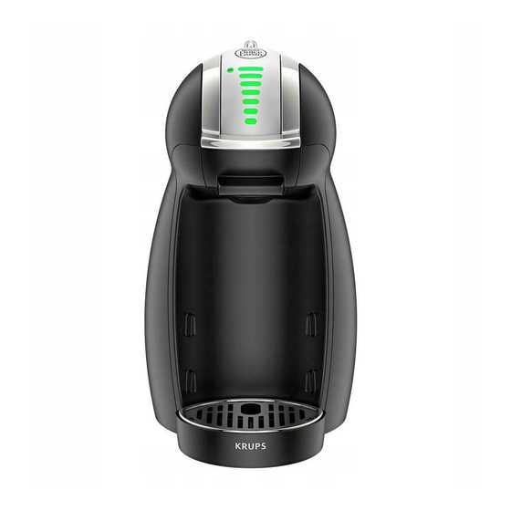
M A I N C O M P O N E N T S M A I N C O M P O N E N T S Overview of external parts This is the Krups machine version which is also shown in the repair chapter. -
Page 6: Overview Of Internal Parts
M A I N C O M P O N E N T S Overview of internal parts 1. Needle plate 8. Main housing 2. Reed sensor (capsule holder detection) 9. NTC temperature sensor 3. Electromagnet 10. Thermo fuses (2x) 4. -
Page 7: Overview Of Rating Plates
M A I N C O M P O N E N T S Overview of rating plates Krups rating plate The rating plate is laser-engraved. TYPE KP160 www.krups.com 220-240V~ 50/60Hz 1340-1600W Do not immerse in water CCCCCCXYZ MADE IN CHINA REF: KP160AAA /7Z0- WWYY R The rating plate •... -
Page 8: De´longhi Rating Plate
M A I N C O M P O N E N T S Longhi rating plate e´ The rating plate is laser-engraved. The rating plate • can be found on the underside of the machine, • carries the following information: EDG = De´Longhi type reference Type number for Genio : 465 / 466 Colour code: B = piano black , S = silver... -
Page 9: Breville Rating Plate (Example)
M A I N C O M P O N E N T S Breville rating plate (example) Genio 2 service manual... -
Page 10: Water Circuit
M A I N C O M P O N E N T S Water circuit 1. Water tank with valve 6. Selection lever 2. Filter and connector 7. F-connector 3. Flow meter 8. Capsule holder 4. Pump 9. Needle plate 5. -
Page 11: Technical Data
M A I N C O M P O N E N T S Technical data Mains voltage Europe (UK, CH, DE, AT, FR, ES, PT, IT, NL, LU, BE, NO, SE, FI, DK, GR, CZ, SK, PL, HU, RU, UA, LT, LV, EE, BG, RO, SI, BiH, SRB, HR)... 230 V / 50 Hz USA / Canada ...................120 V / 60 Hz Japan ....................100 V / 50/60 Hz Mexico, Brazil....................127 V / 60 Hz... - Page 12 M A I N C O M P O N E N T S Various data Pre-heating time ..................approx. 30 sec. Automatic shut off time (eco mode)................5 min Hot beverage outlet temperature........85 °C ± 5 °C (185 °F ± 41 °F) Descaling temperature ..........65 °C to 70 °C (149 °F to 158 °F) Safety temperature for thermo block (thermal cut-off)......
- Page 13 M A I N C O M P O N E N T S Distance from drip grid to coffee outlet [mm] Espresso .......................77 mm Mug ........................120 mm Tall glass ......................150 mm Higher cup (drip tray removed) ................174 mm Genio 2 service manual...
-
Page 14: Operating
O P E R A T I N G O P E R A T I N G Machine status After switching on, an automatic self-test is performed to check if the capsule holder is inserted (with reed sensor) NTC is connected, NTC is not short circuited, the selection lever is in middle position, the thermoblock reaches the working temperature in about 30 seconds. -
Page 15: Bargraph Display
O P E R A T I N G Operating modes Power button Bar graph LED signals Power button: red, rapid blinking with Error mode: 2.5 Hz Thermoblock temperature over Bargraph: segment 7 115 °C (239°F) rapid blinking with 2.5 Hz Bargraph display The bargraph display has 3 different functionalities: 1. -
Page 16: Preparation, First Use
O P E R A T I N G Preparation, first use The new machine has to be rinsed properly before first use according to the following sequence: 1. Rinse water tank at first. 5. Open locking handle and insert The machine will 2. - Page 17 O P E R A T I N G STOP 13. Wait until countdown is finished and 14. Push selection lever up to set the machine stops. bargraph display to maximum level. 15. Move selection lever to the right for hot water rinsing.
-
Page 18: Preparing A Beverage
O P E R A T I N G Preparing a beverage The drip tray is height-adjustable in 3 levels. Choose an appropriate cup size for beverage. Users allergic to dairy products: clean capsule holder under running water 1. Check if water tank is filled. 3. - Page 19 O P E R A T I N G Danger of damage and hot water / product splashes. Do not open locking handle prematurely. 13. Wait until the bargraph display stops 14. Take cup from drip tray. flashing and the power button stops 15.
-
Page 20: Economy Mode
O P E R A T I N G Economy mode After 5 minutes without operation, the machine switches itself OFF automatically. It is not possible to de-activate the This feature helps to save electricity by reducing the amount of power the machine economy mode. - Page 21 O P E R A T I N G In error mode, the power button blinks red and green alternately and the bar- graph segment blinks green. 7. The remaining water drops into the 9. Push selection lever to the right (hot capsule bin.
-
Page 22: Troubleshooting
T R O U B L E S H O O T I N G T R O U B L E S H O O T I N G Checklist The checklist enables you to rapidly locate faults on the machine and to initiate appropriate repair action. Follow the check procedure. - Page 23 T R O U B L E S H O O T I N G Check Further action / Symptoms Action / repair work procedure repair work YES - a) Check if power cord is YES - Go to point b) functional NO - Replace it (see page 43) YES - Go to point c)
- Page 24 T R O U B L E S H O O T I N G Check Further action / Symptoms Action / repair work procedure repair work YES - Fill water tank YES - a) Water tank is empty? NO - Go to point b) YES - b) Water tank is correctly YES - Go to point c) inserted?
- Page 25 T R O U B L E S H O O T I N G Check Further action / Symptoms Action / repair work procedure repair work YES - Perforate capsule only YES - a) Capsule has multiple 6.1 Leakage at extraction once, see user manual perforations? head...
-
Page 26: Repair
R E P A I R R E P A I R General This chapter contains special safety and assembly notes. Non-observance of these notes can lead to injuries and damages! The disassembly and repair procedures are presented as step by step instructions. The position numbers of the parts correspond to the Krups spare parts list. -
Page 27: Tools And Repair Accessories
R E P A I R Tools and repair accessories With the following tools, all described disassembly and repair work can be done: A pin-torx screw head looks like this: Tools Applications Torx screwdriver for security screws, Fastening screws for extraction head, side panels Pin-TX 10 and water tank connector Fastening screw for fuse holder on thermoblock. - Page 28 R E P A I R Danger of injury - sharp pointed needle! The extraction head is adjusted to a specific needle plate. Do not assemble a different needle plates by mistake. 5. Close locking handle (24). 6. Release latch by pressing a suitable pin (dia. 1.8 mm max. e.g. a paper clip) through hole and remove needle plate (5) by pulling it down.
- Page 29 R E P A I R 10. Check and clean outlet of F-connector in particular and needle plate holder in general. 11. Perform a complete descaling resp. rinsing cycle without mounted needle plate. It is important to flush the machine thoroughly prior to the assembly of the needle plate.
-
Page 30: General Disassembly
R E P A I R General disassembly Remove detachable parts Empty fluid system first if hoses have to be disconnected during repair see page 20). Unplug machine from the mains before disassembling - appliance must be isolated! Store cleaning nee- dle (4) at a safe place. - Page 31 R E P A I R Unlatch and remove right side panel 3. Release latch behind power cord first with a screwdriver. At the same time press Releasing this latch right side panel (part of 26) in direction shown. can be difficult. 4.
- Page 32 R E P A I R Latch, pin and recess positions are circled red. Open the 3 delicate latches at the front side by pressing the side cover forward and out- wards. 5. Unlatch right side panel carefully and completely, beginning at the bottom. Genio 2 service manual...
- Page 33 R E P A I R Unlatch and remove left side panel Latch, pin and recess positions are circled red. Open the 3 delicate latches at the front side by pressing the side cover forward and out- wards. 6. Open 2 snap connections at the bottom with the help of a screwdriver (see detail). Lift up left side panel (part of 26) at the same time.
-
Page 34: Replacing Water Tank Connector
R E P A I R Replacing water tank connector 1. Perform general disassembly. 2. Remove water tank connector (9). 3. Pull off silicone hose from flowmeter (12). Assembly tip • Check that filter element and gasket are inserted correctly. Otherwise the water tank can leak or the water tank valve does not open. -
Page 35: Replacing Flowmeter
R E P A I R Replacing flowmeter 1. Perform general disassembly. Use a screwdriver 2. Unplug flowmeter connector from electronic mainboard (22). with flat blade to 3. Lever flowmeter (12) out of housing bottom with a screw driver. lever connector out of 4. -
Page 36: Replacing Pump
R E P A I R Replacing pump Depending on sup- plier, the body of the pump can have dif- ferent colours. Pump 1. Perform general disassembly. Wiring to pump: The flat receptacles have a special connector latching. Press down lever at first, then pull receptacle. 2. - Page 37 R E P A I R The pressure hose to the thermoblock and the clips have to be discarded together with the defect pump. 4. Remove both pressure hoses with clips from pump (7). The pump support is difficult to remove - please be patient.
- Page 38 R E P A I R Alternative disassembly procedure: 6. Press thin blade of a small screwdriver between catch and pump support. 7. Swivel screwdriver to lift the catch and pull pump support (part of 7) out of main housing by hand. Continue disassembly: 8.
-
Page 39: Assembly Tips
R E P A I R Assembly tips • Cut pressure hose from extraction head (23) to pump to 70 mm length according to illustration. to extraction head Make sure that the pieced together pressure hose does not touch the side panels after installation to avoid noise emission. - Page 40 R E P A I R Always use new clips for pressure hose assembly. The white plastic Iid on the pump is rotatable and has a square seat for the fork wrench. • Check that spring (11) is placed under silicone elbow(10). •...
-
Page 41: Replacing Ntc Temperature Sensor
R E P A I R Replacing NTC temperature sensor 1. Perform general disassembly. It is sufficient to 2. Unplug NTC connector from electronic mainboard (22). remove the right side panel only. 3. Loosen and remove screw (Phillips screw, M3 x 5) on thermoblock (13). 4. -
Page 42: Assembly Tips
R E P A I R Assembly tips • Apply a sufficient amount of standard heat conducting paste into NTC-socket of ther- moblock (13). • Make sure that holding plate (see details) lays flat on the socket and does not rest The NTC wire con- on a peg. -
Page 43: Replacing Power Cord With Thermo Fuses
R E P A I R Replacing power cord with thermo fuses Defective thermo fuses can only be replaced together with the power cord. Power cord wires have a country- specific colour code. 1. Perform general disassembly. 2. Loosen 2 screws and remove special strain relief (see detail) if present. This strain relief 3. - Page 44 R E P A I R 5. Loosen screw (Phillips screw, M3 x 5) and remove cable lug (ground connection), fuse holder clip (part of 25) and thermo fuses (part of 25) from thermoblock (13). Genio 2 service manual...
-
Page 45: Assembly Tips
R E P A I R The heatsink on the electronic main- The flat receptacles of the power cord have a special board restricts the access connector latching. to the flat receptacles. Press down lever at first, then pull receptacle. Use a small screwdriver with flat blade to release the lever and unplug the... -
Page 46: Replacing Thermoblock
R E P A I R Danger of short circuit! Do not damage the insulation sleeve on the thermofuse during assembly. • Check power cord wiring according to the wiring diagram (see page 56). • Check wire and cable routing: •... -
Page 47: Assembly Tips
R E P A I R 7. Pull thermoblock (13) with thermoblock holder (21) towards water tank connector (9). Then lift thermoblock holder out of main housing (part of 26). Assembly tips • Assemble thermoblock (13) in thermoblock holder (21): Press down thermoblock and turn it clockwise until bayonet lock engages. - Page 48 R E P A I R • Cut pressure hose from extraction head to thermoblock to 90 mm length according to illustration. Make sure that the to extraction head pieced together pressure hose does not touch the side panels after installation to avoid noise emission.
-
Page 49: Replacing Electronic Mainboard
R E P A I R Replacing electronic mainboard 1. Perform general disassembly. 2. Unplug 7 connectors from electronic mainboard (22). The heatsink on the electronic main- The flat receptacles have a special connector latching. board restricts the access Press down lever at first, then pull receptacle. to the flat receptacles. -
Page 50: Assembly Tips
R E P A I R 5. Remove electronic main board (22) from its support: It is not necessary Press latch on the left side of the support outwards with thumb (see red circle). to remove the print Lift electronic main board out of support at the left side first. Then pull electronic together with the sup- main board out of support laterally. -
Page 51: Replacing Locking Handle And Control Unit
R E P A I R Replacing locking handle and control unit Locking handle and control unit with support can be re-used after replacement of the extraction head. Remove closing handle 1. Perform general disassembly (see page 30). 2. Open locking handle (24). 3. -
Page 52: Replacing Electromagnet
R E P A I R Remove control unit 7. Cut cable tie near electronic mainboard (22). 8. Unplug HMI-connector from electronic mainboard. Replacing electromagnet 1. Perform general disassembly (see page 30). Do not touch the surface of the replacement electromagnet (14) and the bottom of the metal plate (a) without gloves! Otherwise the alignment between these two components can be affected. -
Page 53: Assembly Tip
R E P A I R Assembly tip • Wear gloves for assembly of new electromagnet (14). • Pull connector of electromagnet through opening in extraction head (see red circle). • Insert electromagnet into support. • Press down and hold metal plate (a) on electromagnet (14) so that they are well aligned. -
Page 54: Replacing Extraction Head
R E P A I R Replacing extraction head 1. Perform general disassembly (see page 30). 2. Cut cable tie. 3. Unplug all 5 connectors that are wired with the extraction head (23) from the elec- tronic mainboard (22). 4. Lead these connectors through openings in main housing. 5. -
Page 55: Assembly Tips
R E P A I R Assembly tips • After fastening the new extraction head (23) on the main housing, attach the locking Do not overturn lever (24) with control unit (18) and support (19). Check if locking lever is locked and screws when latch is not broken. -
Page 56: Wiring Diagram
W I R I N G D I A G R A M W I R I N G D I A G R A M Wiring diagram for HMI PCB all mains voltages (100 V, 120 V, 127 V, Pcb for power switch mounting 230 V) On/Off... -
Page 57: Final Testing
F I N A L T E S T I N G F I N A L T E S T I N G The following tests guarantee the correct function of the machine: 1. Heating up time 2. Flow rate (at 8 bar) / water temperature 3. -
Page 58: Heating Up Time
F I N A L T E S T I N G Heating up time 1. Plug into mains and press power 2. Measure the heating up time with a button. stop watch (time until power button stops blinking). Test is passed if power button is turning green - from 25 sec to 40 sec at 230 V mains voltage - or within 60 sec at 100 V / 120 V mains voltage and 50 / 60 Hz mains frequency. - Page 59 F I N A L T E S T I N G 3. Insert capsule holder in machine and Test device assembly close locking handle. 4. Connect T-connector (C) and pres- sure control valve (E) with a flexible tube piece (D, approx. 25 mm long) according to illustration.
-
Page 60: Maximal Pressure / Leakage Check
F I N A L T E S T I N G 30 sec The manometer must be observed continuously and the pressure regulated by using the control valve approx. (E) if necessary. 3 mm With increasing temper- ature the pressure also increases, if necessary readjust the pressure to 8 bar. -
Page 61: Final Inspections
F I N A L I N S P E C T I O N S F I N A L I N S P E C T I O N S General Legal situation Repair centres can be legally obligated to ensure the safety and physical integrity of the Check the legal sit- user/consumer by national regulations and standards. -
Page 62: Safety Instructions
F I N A L I N S P E C T I O N S Safety instructions WARNING Danger of electric shock! Risk of damage to the coffee machine. High test voltage - hazardous situations can arise if a wrong test is selected or a test is executed incorrectly. -
Page 63: Insulation Resistance Test
F I N A L I N S P E C T I O N S 3. Touch thermoblock with test probe (through opening in housing bottom (see detail). 4. Press start button (C) and read off displayed resistance. The resistance must be lower than 0.3 Ohm with a minimal test current of 200 mA. -
Page 64: Earth Leakage Current Test
F I N A L I N S P E C T I O N S 4. Read off displayed insulation resistance between earthing conductor and phase/ neutral conductors. 5. Switch test voltage to test probe (if necessary). 6. Touch with test probe the following test points: - selection lever - locking handle - needle at underside of extraction head (see detail) -
Page 65: Leakage Current Test
F I N A L I N S P E C T I O N S The leakage current in the protective earth connector must be lower than 3.5 mA. Leakage current test This test measures the contact current of touchable metallic parts on the coffee Depending on the machine. -
Page 66: Maintenance
M A I N T E N A N C E M A I N T E N A N C E Descaling Check needle plate (see page 27) prior to descaling: Clean needle plate and deblock needle if necessary. Only use appropriate descaling solution that suits for coffee machine - never use Vinegar! Decalcifier is aggressive to housing surface. - Page 67 M A I N T E N A N C E Instead of the cap- sule bin another container with a capacity of min. 1 litre can be used. 6. Open locking handle and check if 7. Place capsule bin (without insert) capsule holder is empty.
- Page 68 M A I N T E N A N C E The machine can- 2 min not be restarted during waiting time. 16. The machine descales continuously. 18. For a better effect of the descaler, the 17. Wait until countdown is finished and machine enters a waiting time of machine stops.
- Page 69 M A I N T E N A N C E STOP 27. The machine rinses with hot water. 29. The bargraph display switches to 28. Wait until countdown is finished and maximum setting. machine stops. 30. Push selection lever to the left for rinsing of cold water circuit.
-
Page 70: Daily Care And Final Cleaning
M A I N T E N A N C E Daily care and final cleaning Never use detergents to clean the appliance. Do not clean in a dishwasher. Clean the appliance only using soft cleaning cloths, sponges or brushes. The water tank must be cleaned with a baby bottle brush. - Page 71 M A I N T E N A N C E 15. Machine starts rinsing and the 17. Switch off machine. bargraph counts down. 18. Remove and empty capsule bin. 16. Wait until countdown is finished and 19. Clean and wipe dry capsule bin. machine stops.
-
Page 72: Packing Instructions
M A I N T E N A N C E Packing instructions The beverage center and all accessories must be packed in polybags to avoid scratches during transportation. 1. Check if cleaning needle is in 2. Check if capsule holder is inserted. support. - Page 73 M A I N T E N A N C E 6. Stow drip tray in capsule bin. 8. Put pulp trays together. 7. Insert machine and capsule bin in a pulp tray. 9. Insert pulp trays in cardboard box. 10.
-
Page 74: Krups Spare Parts
K R U P S S P A R E P A R T S K R U P S S P A R E P A R T S Genio 2 service manual... - Page 75 K R U P S S P A R E P A R T S Genio 2 service manual...
- Page 76 K R U P S S P A R E P A R T S Genio 2 service manual...
- Page 77 K R U P S S P A R E P A R T S Pos. Part Description WIK Part Number The repair chapter is based on these H connector + Hose clips 9310020100 position numbers. Silicon tube 1M 9310062300 Hose clips 9310062100 Clean spring...
-
Page 78: De´longhi Spare Parts
D E ´ L O N G H I S P A R E P A R T S D E ´ L O N G H I S P A R E P A R T S Genio 2 service manual... - Page 79 D E ´ L O N G H I S P A R E P A R T S Genio 2 service manual...
- Page 80 D E ´ L O N G H I S P A R E P A R T S Genio 2 service manual...
- Page 81 D E ´ L O N G H I S P A R E P A R T S Pos. Part Description WIK Part Number These position numbers do not H connector + 4 Hose clips 9310020100 correspond with the Silicon tube 1m 9310062300 ones in the repair chap-...
- Page 82 D E ´ L O N G H I S P A R E P A R T S Pos. Part Description WIK Part Number 25-5 Power cord cpl. AU 9310319900 25-6 Power cord cpl. UK 9310224000 25-7 Power cord cpl. CH 9310223900 26-1 Kit Housing right &...
-
Page 83: Notes
N O T E S N O T E S Genio 2 service manual...
Need help?
Do you have a question about the BEVERAGE CENTER GENIO 2 and is the answer not in the manual?
Questions and answers