
Related Manuals for Nescafe Dolce Gusto KRUPS KP 2106


Summary of Contents for Nescafe Dolce Gusto KRUPS KP 2106
- Page 1 S E R V I C E M A N U A L B E V E R A G E C E N T E R KRUPS REF.: KP 2106_RED KP 2102_BEIGE KP 2100_BLACK...
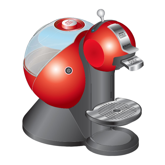
- Page 2 M A I N C O M P O N E N T S M A I N C O M P O N E N T S Overview of external parts 1. Cold water indicator 10. Housing main part 2.
- Page 3 M A I N C O M P O N E N T S Overview of internal parts 1. Cold water pressure hose 7. NTC temperature sensor 2. Hot water pressure hose 8. Thermo fuses (2x) 3. Cable tie 9. Thermoblock 4.
- Page 4 M A I N C O M P O N E N T S Overview of extraction head parts Rear view. 1. Covers 6. Injector plate 2. Axle 7. Reed switch 3. Locking handle 8. Microswitch 4. Selection lever 9. Cold/hot water pressure hoses 5.
- Page 5 M A I N C O M P O N E N T S Overview of rating plate KRUPS KRUPS TYPE KP210X www.krups.com 230V ~50Hz 1500W MADE IN CHINA REF: KP210XYY /7Zx- WWYY R AAAAAXY The rating plate • can be found on the underside of the machine, •...
- Page 6 M A I N C O M P O N E N T S Water circuit 1. Water tank with valve 7. Position hot 2. Filter and connector 8. F-connector 3. Pump 9. Injector plate 4. Thermoblock 10. Capsule holder 5.
- Page 7 M A I N C O M P O N E N T S Technical data Mains voltage Europe (UK, CH, D, AU, F, I, SP, PT, CZ, SK, PL, NL)......230 V / 50 Hz Russia .......................220 V / 50 Hz USA / Canada ...................120 V / 60 Hz Mexico .......................127 V / 60 Hz Brazil ......................127 V / 60 Hz...
- Page 8 M A I N C O M P O N E N T S Various data Pre-heating time..................approx. 30 s Pump pressure max................. 13.5 ± 1.5 bar Noise ......................max. 65 dB(A) Dimensions [mm] Dimensions (D x W x H)..............305 x 214 x 332 mm Power cord length ..................approx.
- Page 9 O P E R A T I N G O P E R A T I N G Machine status After switching on, an automatic self-test is performed to check if the capsule holder is inserted (with reed-switch) NTC is connected, NTC is short circuited, the thermoblock reaches the working temperature within 30 seconds.
- Page 10 O P E R A T I N G Preparation, first use The new machine has to be rinsed properly before first use according to the following A timer or stop sequence: watch is helpful to observe the rinsing times. 1.
- Page 11 O P E R A T I N G 80 sec 10. Set selection lever at position 11. Set selection lever at middle position (hot water). Let water run through to stop rinsing. for approx. 80 sec. 12. Remove and empty jug. 13.
- Page 12 O P E R A T I N G Preparing a beverage Choose an appropriate cup size for beverage. The locking lever can only be 1. Check if water tank is filled. 4. Place a cup under outlet. actuated if the selection 2.
- Page 13 O P E R A T I N G Risk of burning from hot capsule. 11. After power button lights up green: 12. Discard capsule in capsule bin. Do not touch capsule open locking lever and pull out immediately after use. capsule holder.
- Page 14 O P E R A T I N G Empty fluid system for shipping For shipping a machine, it is important to empty the fluid system. The machine will 1. Empty water tank and drip tray. 2. Check that capsule holder is empty. not work without 3.
- Page 15 T R O U B L E S H O O T I N G T R O U B L E S H O O T I N G Checklist The checklist enables you to rapidly locate faults on the machine and to initiate appropriate repair action. Follow the check procedure.
- Page 16 T R O U B L E S H O O T I N G Check Further action / Symptoms Action / repair work procedure repair work YES - a) Check if magnets of YES - Go to point b) capsule holder are in place.
- Page 17 T R O U B L E S H O O T I N G Check Further action / Symptoms Action / repair work procedure repair work 4 Plug into mains 4.4 Machine is hissing if valve YES - Replace the extraction head and switch ON handle is in middle position NO - Go to point 5...
- Page 18 T R O U B L E S H O O T I N G Check Further action / Symptoms Action / repair work procedure repair work YES - Perforate the capsule YES - a) The capsule has multiple only once, see user manual 6.1 Leakage at extraction head perforations? NO - Replace the extraction...
- Page 19 R E P A I R R E P A I R This chapter contains special security and assembling notes. Non-observance can lead to injuries and damages! Tools and repair accessories With the following tools, all described repair work can be done: A pin-torx screw •...
- Page 20 R E P A I R Removing injector plate, de-blocking of injector Solid residues in the water circuit can block the injector completely. An example is the development of calcium particles if the machine is not descaled periodically. Therefore this error appears during descaling frequently. Danger of injury - sharp pointed injector (D)!
- Page 21 R E P A I R 5. Clear blocked bore of injector (F). Use a pin or needle with dia. 0.6 mm max. to clear the injector bore. Alter- natively a piece of polyamid fishing line or nylon monofilament with suit- able diameter can be used.
- Page 22 R E P A I R Assembly information 1. Insert the same injector plate with rear side first. Do not exchange 2. Then press injector plate against plate holder till latch at the front side engages. the injector plate.
- Page 23 R E P A I R General disassembly information All outer parts are assembled with special screws. Please insert the same screws when reassembling the machine - for safety reasons for the user. • Empty the fluid system before repair (if possible) and shipment. WARNING Danger of electric shock - live parts inside coffee machine.
- Page 24 R E P A I R Unplug machine from the mains before disassembling - appliance must be isolated! 1. Remove water tank (A), capsule holder (B) and drip tray (C) together with drip grid. If leakages occur, perform the pres- sure test with leakage check (see page 37).
- Page 25 R E P A I R Replacing water filter and water tank connector 1. Remove silicone elbow (F) from filter element (I). To replace silicone 2. Set blade of a screwdriver on bordering of filter element (I). Press down filter elbow (F) refer to element on one side with screwdriver.
- Page 26 R E P A I R Assembling a new NTC temperature sensor 1. Follow partial disassembly (see page 26). 2. Unplug NTC connector (J) from electronic mainboard (K). 2 different NTC temperature sensor types can be mounted on the thermoblock. 3.
- Page 27 R E P A I R 4. Apply a sufficient amount of standard heat conducting paste into socket (M). 5. Attach a new clamp spring (N) on the nw NTC temperature sensor (L). Use a pair of pliers to fix the spring. 6.
- Page 28 R E P A I R 10. If NTC temperature sensor (L) is glued in thermoblock: Cut off connecting cable next to the sensor body. 11. Mount new NTC temperature sensor with a clamp spring in thermoblock socket (M) according to page 30. Assembly information •...
- Page 29 R E P A I R Replacing electronic main board with power button The power button is part of the PCB assembly and cannot be replaced separatedly. Valve Safety Heater Neutral Pump Line 1. Follow partial disassembly (see page 26). 2.
- Page 30 R E P A I R Making fast a shaky extraction head After impact stress, falling down, holding the extraction head and lifting the machine etc. the latch connection to the housing main part can become loose. The neck of the extraction head can be mounted on the hous- ing main part with 2...
- Page 31 R E P A I R Replacing extraction head 1. Follow partial disassembly (see page 26). 2. Cut through both hoses (U) on the same level near the opening of the extraction head. Do not cut through the hoses near the electronic main board! After re-assembly the metallic clips of the H-connector can get in contact with electronic components and cause malfunctions.
- Page 32 R E P A I R Valve Safety 4. Unplug wiring of extraction head from electronic main board (K) - valve connector (O, to microswitch) - safety connector (P, to reed switch) The new extraction head is delivered without selection lever and locking handle. These parts have to be detached from the defect extraction head.
- Page 33 R E P A I R 6. Use a screwdriver no. 1 to remove shutter assembly (X). During the removal of the extraction head covers, latches will be bent or destroyed almost certainly. Therefore this covers cannot be re-used. For easy recogni- tion, the latches are color coded in the illus- tration.
- Page 34 R E P A I R 9. Release latch with screwdriver (see detail) and pull off locking handle (Z). 10. Remove extraction head from coffee machine by releasing 2 latches (d, steps 1 and 2): Push away neck side walls one after the other from housing main part with a screw- driver.
- Page 35 R E P A I R Assembly information for new extraction head A new extraction head is equipped with extended pressure hoses and an additional H connector for test pur- poses. 11. Cut off excessive length of pressure hoses (U) from new extraction head. For trouble-free reconnection of pressure hoses, observe cutting distances (see page 34 and above).
- Page 36 R E P A I R Valve Safety 16. Plug wiring of extraction head in electronic main board (K) - valve connector (O, from microswitch) - safety connector (P, from reed switch) 1. Snap in locking handle (Z). 2. Open locking handle. 3.
- Page 37 R E P A I R 5. Snap in shutter assembly (X): As first step pull out shutter strip (g) on one side and insert it in opening. As second step snap in other side of the shutter assembly (with inserting short end of shutter strip at first).
- Page 38 R E P A I R Full disassembly A full disassembly is based on the partial disassembly, is only necessary to repair resp. replace thermoblock, pump with silicone elbow or power cord with thermo cut off fuses. 1. Perform partial disassembly first (see page 26). 2.
- Page 39 R E P A I R The flat receptacles have a special connector latching. Press down lever at first, then pull receptacle. 7. Cut through both hoses (H) on the same level near the opening of the extraction A H-connector head.
- Page 40 R E P A I R Make sure that all wires are discon- nected from electronic main board. 8. Release 4 latches ( I ) with the help of a screwdriver. Press down on 9. Lift up the housing main part with extraction head. thermoblock or pump simultaneously to prevent that the latches...
- Page 41 R E P A I R Replacing thermoblock 1. Perform full disassembly first (see page 41). Pay attention to 2. Unplug electical connection (J) from thermoblock (K). residual water flow- 3. Remove clamp and pressure hose (L) from thermoblock. ing out from the ther- moblock.
- Page 42 R E P A I R 5. Press thermoblock (K) down at housing bottom (Q) and turn it clockwise till limit stop (see top view). 6. Lift off thermoblock from support (R, part of housing bottom). 7. Check if support has melting marks due to overheating of defect thermoblock. Replace housing bottom (Q) if thermoblock support is damaged.
- Page 43 R E P A I R Replacing pump Depending on sup- pliers, the body of the pump can have 3 dif- ferent colors. 1. Perform full disassembly first (see page 41). 2. Unplug flat receptacle (R) from pump (S). The flat receptacle has a special connector latching. Press down lever at first, then pull receptacle.
- Page 44 R E P A I R 5. Press down 2 latches (V) with screwdriver 6. Pull out rubber strap (W) together with pump. 7. Remove rubber strap from pump. It is possible to 8. Replace defective pump. remove resp. mount the rubber strap without unscrewing the Assembly information Y-connector (Y) of the...
- Page 45 R E P A I R Replacing power cord with thermo fuses Defective thermo fuses can only be replaced together with the power cord. 1. Perform full disassembly first (see page 41). 2. Loosen 2 screws (Z) and remove strain relief (a). 3.
- Page 46 R E P A I R General assembly information • Connect the separated hoses with a H-connector (c, see detail): Do not interchange Push the hoses to the stop on the H-connector and set the hose clips in the middle the pressure hoses! position.
- Page 47 W I R I N G D I A G R A M S W I R I N G D I A G R A M S Wiring diagram 230 V - EU...
- Page 48 W I R I N G D I A G R A M S Wiring diagram 120 V - UL...
- Page 49 W I R I N G D I A G R A M S Wiring diagram 100 V - Japan...
- Page 50 F U N C T I O N T E S T S F U N C T I O N T E S T S The following function tests guarantee the correct function of the machine: • Heating up time •...
- Page 51 F U N C T I O N T E S T S Heating up time If the heating up time is more than 40 sec., change the elec- tronic main board. ~ 30 sec 1. Plug into mains and press power 2.
- Page 52 F U N C T I O N T E S T S Measuring temperature of hot beverage 1. Switch machine ON. 4. Insert capsule holder in machine and 2. Place a measuring beaker under close locking lever. outlet. 5. Set selection lever at position 3.
- Page 53 F U N C T I O N T E S T S Measuring flow rate of hot beverage START 1. Switch machine ON. 4. Insert capsule holder and push it 2. Place a measuring beaker under down. outlet. 5. Set selection lever at position 3.
- Page 54 F U N C T I O N T E S T S Moving force of selection lever 1. Switch machine ON. 3. After heating up, set selection lever 2. Place a recipient under outlet. at positions (cold) and (hot) separately.
- Page 55 M A I N T E N A N C E M A I N T E N A N C E Descaling Do not interrupt Only use KRUPS descaling powder (F054) - never vinegar! descaling proce- Decalcifier is aggressive to surface of casing. dure.
- Page 56 M A I N T E N A N C E 45 sec 5 sec 7. Press and hold power button for at 8. Set selection lever at position least 5 sec, till it starts blinking. (hot). 9. Let hot descaling solution flow into jug for 45 sec.
- Page 57 M A I N T E N A N C E 5 min 14. Set selection lever at middle position 16. Remove and empty jug. (stop). 17. Remove, rinse and clean water tank. 15. Wait for 5 minutes. 45 sec 18.
- Page 58 M A I N T E N A N C E 45 sec 23. Set selection lever at position 25. Set selection lever at middle position (cold). (stop). 24. Let cold water flow into jug for 26. Switch machine OFF. 45 sec.
- Page 59 M A I N T E N A N C E Daily care and final cleaning Never use detergents to clean the appliance. Clean the appliance only using soft cleaning cloths, sponges or brushes. The water tank must be cleaned with a baby bottle brush.
- Page 60 M A I N T E N A N C E 10 sec 10. Place a jug with enough capactiy 12. Rinse machine with hot water for under outlet. 10 sec. 11. Check that - locking handle is closed, - machine is switched on. 13.
Need help?
Do you have a question about the KRUPS KP 2106 and is the answer not in the manual?
Questions and answers
JAKA WARTOŚĆ NTC W 20 STOPNIACH CENCJUSZ