Minebea Intec PR 5900 Series Instrument Manual
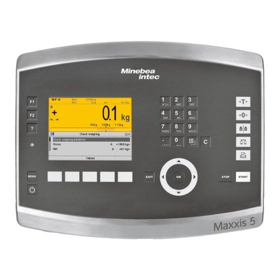
Remote terminal for maxxis 5
Hide thumbs
Also See for PR 5900 Series:
- Operating instructions manual (382 pages) ,
- Original installation manual (138 pages)
Table of Contents
Advertisement
Quick Links
Advertisement
Table of Contents

Related Manuals for Minebea Intec PR 5900 Series


Summary of Contents for Minebea Intec PR 5900 Series
- Page 1 Instrument Manual Remote Terminal for Maxxis 5 PR 5900/61, ../71 Translation of the Original Instrument Manual 9499 050 59800 Edition 2.3.0 09/07/2020 Release 1.00.xx Minebea Intec GmbH, Meiendorfer Str. 205 A, 22145 Hamburg, Germany Phone: +49.40.67960.303 Fax: +49.40.67960.383...
- Page 2 Any information in this document is subject to change without notice and does not represent a commitment on the part of Minebea Intec unless legally prescribed. This product should only be operated/installed by trained and qualiied personnel. In correspondence concerning this product, the type, name, and release number/serial number as well as all license numbers relating to the product have to be cited.
-
Page 3: Table Of Contents
Overview of connections ............................14 Device versions ................................15 Device installation..........................16 General notes ................................16 Control cabinet equipment ............................. 16 Table-top devices ..............................17 4.3.1 Cable gland ..............................17 4.3.2 Installation of a cable ............................ 19 EMC-compliant installation ............................20 Minebea Intec EN-1... - Page 4 Display ................................41 9.2.2 Supply voltage connection 24 V DC......................41 Efect of ambient conditions ..........................41 9.3.1 Ambient conditions ............................41 9.3.2 Electromagnetic Compatibility (EMC)......................42 9.3.3 RF interference suppression ........................42 Mechanics ..................................42 9.4.1 Design................................42 9.4.2 Dimensions ..............................42 EN-2 Minebea Intec...
- Page 5 Remote Terminal for Maxxis 5 PR 5900/61, ../71 Table of contents 9.4.3 Weights................................42 Documentation on the CD included ........................42 Appendix ............................43 10.1 Certiicates.................................43 Minebea Intec EN-3...
-
Page 6: Introduction
WARNING indicates that death or severe, irreversible injury may occur if appropriate safety measures are not observed. Take the corresponding safety precautions. CAUTION Warning of personal injury. CAUTION indicates that minor, reversible injury may occur if appropriate safety measures are not observed. Take the corresponding safety precautions. EN-4 Minebea Intec... -
Page 7: Hotline
NOTICE indicates that damage to property and/or the environment may occur if appropriate safety measures are not observed. Take the corresponding safety precautions. Note: User tips, useful information, and notes. Hotline Phone: +49.40.67960.444 Fax: +49.40.67960.474 eMail: help@minebea-intec.com Minebea Intec EN-5... -
Page 8: Safety Instructions
If there are grounds for rejection of the goods, a claim must be iled with the carrier immediately. The Minebea Intec sales or service organization must also be notiied. EN-6 Minebea Intec... -
Page 9: Before Operational Startup
Cables are connected to the electronics at the back of the housing. 2.5.2.2 Table-top housing A base plate is located on the underside of the housing (see arrow). This plate must be removed to connect the screw-in cables to the electronics. Minebea Intec EN-7... -
Page 10: Supply Voltage Connection
Make sure that the construction of the device is not altered to the detriment of safety. In particular, leakage paths, air gaps (of live parts) and insulating layers must not be reduced. Minebea Intec cannot be held responsible for personal injury or property damage caused by a device repaired incorrectly by an operator or installer. EN-8... -
Page 11: Repairs And Maintenance
General information Repairs are subject to inspection and must be carried out at Minebea Intec. In case of defect or malfunction, please contact your local Minebea Intec dealer or service center for repair. When returning the device for repair, please include a precise and complete description of the problem. -
Page 12: Remote Terminal
A 24 V power supply is required for the electrical supply. Housing 3.3.1 General notes The following housing options are available: Stainless steel housing for the switchbox installation (for PR 5900/61), see Chapter 3.3.2.1 Stainless steel housing for table-top mounting (for PR 5900/71), see Chapter 3.3.2.2 EN-10 Minebea Intec... -
Page 13: Dimensions
The keypad and the display form one unit with the front. A rectangular cut-out is required for the installation. Cable connections are made at the back of the housing. Front view Side view All dimensions in mm All dimensions in mm Minebea Intec EN-11... - Page 14 All dimensions in mm 3.3.2.1.1 Drilling template and control panel cut-out The drilling template (shown in a reduced size) with control panel cut-out is included as an original in the scope of supply. 65997-220-91 All dimensions in mm EN-12 Minebea Intec...
- Page 15 The keypad and the display form one unit with the front. The cables are fed through entry glands on the bottom of the housing and connected to the electronics. Front view Side view, turned * approximations All dimensions in mm Back view Minebea Intec EN-13...
-
Page 16: Overview Of Connections
4 x digital output (passive) Dig/out B Dig/in A 4 x digital input (active) Dig/in B For Ex applications only! Interface RS-485 Connection for xBPI platforms RS-485 interface Host Connection for the Maxxis 5 Dedicated Ethernet connection EN-14 Minebea Intec... -
Page 17: Device Versions
CAT5 S/FTP data cable, with 4 wires, braided, e.g., Host cable EtherLine®-P CAT. 5 2x2x24AWG Cable with cable gland: Designation Maxxis 5 CAT5 S/FTP data cable, with 4 wires, braided, e.g., Host cable EtherLine®-P CAT. 5 2x2x24AWG Minebea Intec EN-15... -
Page 18: Device Installation
Ingress of dirt through the air vent in the housing. There is a risk of damage being caused to the device. Ensure that dirt does not enter the device when performing mechanical work on it and/or in its vicinity. EN-16 Minebea Intec... -
Page 19: Cable Gland
For full IP protection, operation with the dust protection cover itted is not permitted. Remove the dust protection cover. If a cable gland is not used, it must be sealed with a supplied locking pin. Minebea Intec EN-17... - Page 20 "LC 6" load cell "LC 4" load cell "LC 2" load cell "WP" port for the weighing electronics in the Maxxis 5 "PS/2" port for the external PC keyboard Digital outputs "Dig/out A" Digital outputs "Dig/out B EN-18 Minebea Intec...
-
Page 21: Installation Of A Cable
6. Tighten the sleeve screw cap (1). 7. Secure the gland (6) including the o-ring (7) using the counter nut (in the housing). NOTICE Material damage is possible. Regularly check the cable gland for tightness and re-tighten it, if necessary. Minebea Intec EN-19... -
Page 22: 4.4 Emc-Compliant Installation
Connecting the screens to the screen clamping rail The screens must be connected to the screen clamping rail using cable clamps as pictured or the supplied screen terminals. 4.4.2 Connecting the equipotential bonding conductor The equipotential bonding conductor (1) must be connected as pictured. EN-20 Minebea Intec... -
Page 23: Hardware Construction
"Dig/in A" and "Dig/in B" digital inputs For Ex applications only: "TTY" connection for barcode scanners with Ex approval "RS 485" connection for xBPI scale "Host" connection for Maxxis 5 The color-graphic display is connected to the main board via a ribbon cable. Minebea Intec EN-21... -
Page 24: Maxxis 5 Connection
4.5.2 Maxxis 5 connection A dedicated Ethernet connection (permanent point-to-point connection) is used for data transfer between Maxxis 5 ("Remote Terminal" interface) and the remote terminal ("Host" interface). ① Screen ② Screen clamping rail or cable gland EN-22 Minebea Intec... -
Page 25: Rs-485 Interface
Connection values see Option CX1 additional information 4.5.3 RS-485 interface The device is equipped with an integrated RS-485 interface. Using this interface, it is possible to connect a platform scale with xBPI protocol. Back, right Block diagram RS-485 Minebea Intec EN-23... - Page 26 ③ 14-pin male connector ④ Screen ⑤ Cable gland or screen clamping rail Coniguration PR 5900 [Operating] - [System setup] - [Weighing points] - [Weighing point X] - [xBPI scale] - [In- terface] - [Remote terminal RS‑485] EN-24 Minebea Intec...
-
Page 27: Digital Inputs
4 Device installation Remote Terminal for Maxxis 5 PR 5900/61, ../71 Note: For further information, see the platform scale operating instructions. 4.5.4 Digital inputs 4 active inputs are permanently built into the device for process control. Minebea Intec EN-25... - Page 28 Max. 150 m Coding pin Is inserted in the position marked in gray in the image Connection values See certiicates on the CD included Example: Connection: Contact input "active" ① Dig/in A ② Screen clamping rail or cable gland EN-26 Minebea Intec...
-
Page 29: Digital Outputs
4 passive opto-decoupled outputs are permanently built into the device. An external power supply is required. Technical data Description Data Connection 2 x terminal, 4-pin; clamping area 0.2 to 1.5 mm Number of outputs 4 (CH1, CH2, CH3, CH4) Minebea Intec EN-27... -
Page 30: Ps/2 Interface
Terminal, 4-pin; clamping range 0.2–1.5 mm Type PS/2 Coding pin is inserted into the position marked gray in the image (in this case pin 1) Connection values See external keyboard’s operating manual Block diagram PS/2 Back, right EN-28 Minebea Intec... - Page 31 You can set the keyboard layout for the connected keyboard under menu item [Operating] - [System Setup] - [Operating Parameters] - [External Keyboard Layout] : [German QWERTZ] [French AZERTY] [Italian QWERTY] [Spanish QWERTY] [English QWERTY] [Russian QWERTY/йцукен] Minebea Intec EN-29...
-
Page 32: Connecting A Power Supply
Technical data Description Data Connection Terminal, 3-pin Rated voltages 24 V Supply voltage 24 V/1 A ±10% max. cable length Dependent on cable gage Connection values See certiicates on CD included Back, middle Connection ①24 V power adapter EN-30 Minebea Intec... -
Page 33: Connecting Weighing Electronics Board "W1" To Maxxis 5
The cable screen must be connected in the metal sleeve of the cable gland or to the screen clamping rail (Control Cabinet device). Terminal Connection Description + Meas. + Signal/LC output - Meas. - Signal/LC output + Supply + Supply/excitation + Sense + Sense - Sense - Sense - Supply - Supply/excitation Minebea Intec EN-31... -
Page 34: Analog Connections
There are connections for a maximum of 6 analog load cells on the housing rear panel. Note: Do not shorten the load cell cable. Connect the prepared cable end and roll up the remaining cable. Terminal Connection (color) Description green Signal/LC output gray Signal/LC output Supply/excitation white Sense black Sense blue Supply/excitation EN-32 Minebea Intec... -
Page 35: Connecting A Load Cell With A 4-Wire Cable
4 Device installation Remote Terminal for Maxxis 5 PR 5900/61, ../71 4.5.10 Connecting a load cell with a 4-wire cable ① Link closed ② Link closed ③ Screen ④ Screen clamping rail or cable gland ⑤ Equipotential bonding conductor Minebea Intec EN-33... -
Page 36: Connecting A Load Cell With A 6-Wire Cable
Remote Terminal for Maxxis 5 PR 5900/61, ../71 4 Device installation 4.5.11 Connecting a load cell with a 6-wire cable ① Link open ② Link open ③ Screen ④ Screen clamping rail or cable gland ⑤ Equipotential bonding conductor EN-34 Minebea Intec... -
Page 37: Getting Started
The following display appears when the remote terminal is switched on. Once the connection has been established, the screen content of the Maxxis 5 is displayed. A connection can only be established during normal operation of the Maxxis 5. Minebea Intec EN-35... -
Page 38: Assigning A Speciic Maxxis 5 And Remote Terminal
Check that the Maxxis 5 is in normal operating mode and not in BIOS, for example. Check cable connections. Assigning a speciic Maxxis 5 and remote terminal Requirement: The remote terminal is in online mode, i.e. the screen content of the Maxxis 5 is displayed. EN-36 Minebea Intec... -
Page 39: Procedure For Operation In Legal Metrology
The calibration check number is always saved in the remote terminal. Changes are possible. A new check number is saved after each save. Switching of the device Switching of the device, refer to the PR 5900 operating manual. Minebea Intec EN-37... -
Page 40: Repairs And Maintenance
Repairs Repairs are subject to inspection and must be carried out at Minebea Intec. In case of defect or malfunction, please contact your local Minebea Intec dealer or service center for repair. When returning the device for repair, please include a precise and complete description of the problem. -
Page 41: Disposal
We reserve the right not to accept products that are contaminated with hazardous substances (ABC contamination) for repair. Should you have any further questions, please contact your local service representative or our service center. Minebea Intec GmbH Repair center Meiendorfer Strasse 205 A 22145 Hamburg, Germany Phone: +49.40.67960.666... -
Page 42: Error Correction
"frozen" and a message is displayed. the digital outputs are reset. The symbol appears in the status display on the Maxxis 5. Check that the Maxxis 5 is in normal operating mode and not in, e.g. BIOS. 2. Check cable connections. EN-40 Minebea Intec... -
Page 43: Technical Data
Current number 30 = Hamburg 252* = April 2010 * Is increment according to the year group table of Minebea Intec. General data The following characteristics are valid after a warm-up time of at least 60 minutes (reference temperature 23 °C). -
Page 44: Electromagnetic Compatibility (Emc)
Control cabinet housing 3.0 kg Approx. 4.0 kg Table-top housing 5.7 kg Approx. 6.7 kg Documentation on the CD included The documents and manuals listed in the appendix (see Chapter 10.1) can be found on the PR 5900 CD. EN-42 Minebea Intec... - Page 45 10 Appendix Remote Terminal for Maxxis 5 PR 5900/61, ../71 10 Appendix 10.1 Certiicates Ser. no. Description Document no. EU-Declaration of Conformity MEU17033 The documents listed in the table can be found on the PR 5900 CD. Minebea Intec EN-43...
- Page 46 Published by Minebea Intec GmbH | Meiendorfer Strasse 205 A | 22145 Hamburg, Germany Phone: +49.40.67960.303 | Email: info@minebea-intec.com www.minebea-intec.com...
Need help?
Do you have a question about the PR 5900 Series and is the answer not in the manual?
Questions and answers