Table of Contents
Advertisement
Advertisement
Table of Contents

Related Manuals for Tech Controllers EU-L-4 WIFI


Summary of Contents for Tech Controllers EU-L-4 WIFI
- Page 1 Eu-l-4 wifi...
-
Page 2: Table Of Contents
TABLE OF CONTENTS Safety ..................................4 Description of the device ............................5 III. How to install the controller ............................. 6 Main screen description ............................8 WiFi screen ................................8 Screen - zone ................................9 Screen – additional contacts ........................... 9 Controller menu............................... - Page 3 Statistics tab ................................24 Settings tab ................................24 VII. Software update ..............................25 VIII. Protections and alarms ............................25 Technical data ................................27 KN.2020.09.23...
-
Page 4: Safety
SAFETY Before using the device for the first time the user should read the following regulations carefully. Not obeying the rules included in this manual may lead to personal injuries or controller damage. The user’s manual should be stored in a safe place for further reference. -
Page 5: Description Of The Device
II. DESCRIPTION OF THE DEVICE The L-4 WiFi controller is intended for controlling the heating device. It controls the heating device and the valve actuators which regulate the water flowing to the maximum of 8 CH zones. The device has a built-in WiFi module enabling the user to view and edit the controller parameters using a mobile app eModul. -
Page 6: How To Install The Controller
III. HOW TO INSTALL THE CONTROLLER The controller should be installed by a qualified person. 1. EXIT button – exit the menu, cancel the settings, choose the screen view (WiFi, Zones, Additional contacts). 2. – (minus) button – view menu functions, decrease the value while editing parameters. 3. - Page 7 WARNING Risk of fatal electric shock from touching live connections. Before working on the controller switch off the power supply and prevent it from being accidentally switched on. NOTE Sensor cables and supply cables should be connected to proper inputs. The diagrams below show example systems:...
-
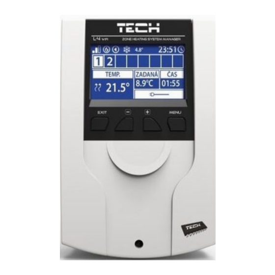
Page 8: Main Screen Description
IV. MAIN SCREEN DESCRIPTION At the first start-up the controller shows WiFi network screen. The screen view may be changed by pressing EXIT button and selecting a different screen. WIFI SCREEN Network status Network name Day of the week Date Time WiFi signal strength... -
Page 9: Screen - Zone
SCREEN - ZONE Pre-set zone temperature Current zone temperature (two arrows pointing up indicate heating). Zone number WiFi signal strength Active voltage-free contact (MW-1) Active pump Current external temperature. When the temperature outside drops below 5°C, a snowflake icon is displayed on the left. -
Page 10: Controller Menu
Day of the week Date Time Zones in which the contact is registered Contact signal strength V. CONTROLLER MENU BLOCK DIAGRAM – MAIN MENU Normal mode Zones 1-8 Holiday mode Operation modes Economical mode Comfort mode Registration External sensor Calibration Built-in contact External contact Floor pump... -
Page 11: Zones
ZONES This submenu enables the user to configure operation parameters for particular zones REGISTRATION This function enables the user to register the C-8r, C-mini or CL-mini sensor or the R-8b, R-8bw regulators. It is also possible to register the C-8f floor sensor as a zone sensor. As a consequence, the zone control will be based on floor temperature. -
Page 12: Pre-Set Temperature
2.5. PRE-SET TEMPERATURE The pre-set zone temperature depends on the weekly schedule settings. The user may also change this value separately. After the value has been set, the user defines how long the temperature should apply. When the time elapses, the pre- set temperature depends on the weekly schedule again. -
Page 13: Window Sensors
Example: Pre-set zone temperature: 23˚C Minimum opening: 30% Maximum opening: 90% Range: 5˚C Hysteresis: 2˚C In the above example, the thermostatic valve starts closing at the temperature of 18˚C (pre-set value minus Range). The minimum opening is reached when the zone temperature reaches the pre-set value. Once the pre-set temperature has been reached, the temperature starts falling. -
Page 14: Operation Modes
Settings – This function is used to activate the window sensor (possible after sensor registration) and set the delay time. When the pre-set delay time is over, the main controller sends the information to the actuators forcing them to close. -
Page 15: Voltage-Free Contact
- register a wireless additional pump contact (executive module) - switch off a given zone - set up activation delay (if the temperature in a given zone is too low, the contact will be enabled after the delay time). VOLTAGE-FREE CONTACT This function enables the user to register wireless module MW-1. -
Page 16: Time Settings
8.2. TIME SETTINGS The current time and date are automatically downloaded from the network. The user can switch the synchronization to manual mode. 8.3. SCREEN SETTINGS These parameters enable the user to customize the screen settings to satisfy individual needs. The user may choose the data to be displayed in the main screen view ... -
Page 17: System Control Via The Internet
VI. SYSTEM CONTROL VIA THE INTERNET The emodul.eu website offers a wide range of possibilities to control the heating system. In order to take full advantage of it, it is necessary to create an account: Once logged in, go to Settings tab and select Register module. Next, enter the code generated by the controller (to generate the code, select Registration in the controller menu). -
Page 18: Home Tab
HOME TAB The Home tab displays the main screen with tiles illustrating the current status of particular heating system devices. Tap on the tile to adjust the operation parameters: NOTE „No communication” message means that the communication with the temperature sensor in a given zone has been interrupted. - Page 19 The upper value is the current zone temperature whereas the bottom value is the pre-set temperature The pre-set zone temperature depends by default on the weekly schedule settings. Constant temperature mode enables the user to set a separate pre-set temperature value which will apply in the zone regardless of the time. Selecting Constant temperature icon, the user may choose the temperature with time limit.
- Page 21 Tap on Schedule icon to open up the weekly schedule selection screen: Two types of weekly schedules are available in the controller 1. Local schedule It is a weekly schedule assigned to a particular zone. Once the controller detects the room sensor, the schedule is assigned automatically to the zone.
- Page 22 After selecting the schedule press OK and move on to edit the weekly schedule settings: Editing each schedule enables the user to define two programs and select days when the programs will be active (e.g. from Monday to Friday and the weekend). The starting point for each program is the pre-set temperature value. For each program the user may define up to 3 time periods when the temperature will be different from the pre-set value.
-
Page 23: Zones Tab
ZONES TAB The user may customize the home page view by changing zone names and corresponding icons. In order to do it, go to Zones tab: FITTER’S MENU TAB The Fitter’s menu tab enables the user to configure the parameters of: ... -
Page 24: Statistics Tab
STATISTICS TAB Statistics tab enables the user to view the temperature values for different time periods e.g. 24h, a week or a month. It is also possible to view the statistics for the previous months: SETTINGS TAB Settings tab enables the user to register a new module and change the e-mail address or the account password:... -
Page 25: Software Update
VII. SOFTWARE UPDATE In order to conduct the software update, follow these steps: 1. Disconnect the controller from the power supply 2. Insert a flash drive with new software into the USB port. 3. Connect the controller to the power supply. 4. - Page 26 STT-869 actuator alarm Error #1 - Calibration error 1 – Moving the screw to the - The limit switch sensor is damaged - Call the service staff mounting position took too much time - The actuator has not been screwed - Check if the controller has been Error #2 - Calibration error 2 –...
-
Page 27: Technical Data
IX. TECHNICAL DATA Power supply 230V +/- 10% / 50Hz Max. Power consumption Ambient temperature 5°C ÷ 50°C Sensor thermal resistance -30°C ÷ 50°C Outputs 1-4 load 0,5A Potential-free contact max. output load Frequency 868MHz Fuse 3,15A Transmission IEEE 802.11 b/g/n EU Declaration of conformity Hereby, we declare under our sole responsibility that controller L-4 WiFi manufactured by TECH, head-quartered in Wieprz Biała Droga 31, 34-122 Wieprz, is compliant with Directive 2014/53/EU of the European parliament and of the...
Need help?
Do you have a question about the EU-L-4 WIFI and is the answer not in the manual?
Questions and answers