
Related Manuals for Vislink DXL5000 TX


Summary of Contents for Vislink DXL5000 TX
- Page 1 DXL5000 Digital Microwave System User and Technical Manual Manual Part No. 400571-1 Rev. B March 2010...
- Page 2 The foregoing does not apply to vendor proprietary parts. Vislink has made every effort to ensure the accuracy of the material contained in this manual at the time of printing. As specifications, equipment, and this manual are subject to change without notice, Vislink assumes no responsibility or liability whatsoever for any errors or inaccuracies that may appear in this manual or for any decisions based on its use.
-
Page 3: Table Of Contents
Contents 1 About the DXL5000 1.1 DXL5000 Transmitter Displays and Connections - - - - - - - - - - - - - - - - - - - - 1-2 1.2 DXL5000 Receiver Displays and Connections - - - - - - - - - - - - - - - - - - - - - - 1-4 1.3 Getting Support for Your DXL5000 - - - - - - - - - - - - - - - - - - - - - - - - - - - - - - 1-6 1.3.1 Supported Repairs - - - - - - - - - - - - - - - - - - - - - - - - - - - - - - - - - - - - - 1-6 1.3.2 Replacement Parts - - - - - - - - - - - - - - - - - - - - - - - - - - - - - - - - - - - - - 1-6... - Page 4 A DXL5000 Specifications A.1 DXL5000 Connectors - - - - - - - - - - - - - - - - - - - - - - - - - - - - - - - - - - - - - - - A-1 A.1.1 AC Power Connection - - - - - - - - - - - - - - - - - - - - - - - - - - - - - - - - - - - A-1 A.1.2 MGMT Connections - - - - - - - - - - - - - - - - - - - - - - - - - - - - - - - - - - - - A-1 A.1.3 IF IN, IF MON, ASI/DS3/E3, ASI3/SMPTE310 BNC Connectors - - - - - A-1...
-
Page 5: About The Dxl5000
About the DXL5000 The DXL5000 consists of a digital microwave transmitter and a digital microwave receiver and is a cost-effective, highly reliable, flexible, and compact microwave link for the following long-haul and medium-haul applications, such as: Studio-to-Transmitter Links (STL) Transmitter-to-Studio Links (TSL) Multi-hop and multi-channel broadcast, Community Antenna Television (CATV) Standard Definition Television (SDTV) -
Page 6: Dxl5000 Transmitter Displays And Connections
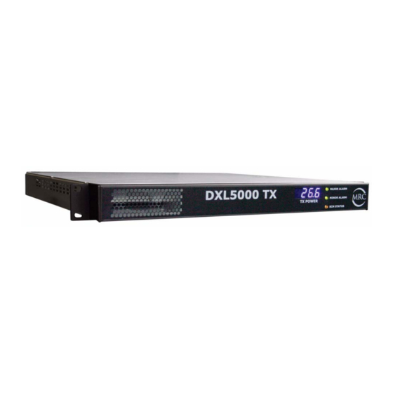
1.1 DXL5000 Transmitter Displays and Connections The following figure and associated table shows the DXL5000 transmitter displays and connectors. 15 16 17 TX POWER Indicates the current transmitter output power level in LCD display dBm. ALARM • MAJOR ALARM—Indicates a condition that can interrupt LEDs service. - Page 7 IMC BUS (Reserved for future use.) pin male D connector WAYSIDE DATA Provides RS-232 input for wayside data transmission via the SCM modem. pin male D connector ASI 3/SMPTE310 Provides a third ASI input or SMPTE310 service input to the 75 Ohm BNC female connector unit.
-
Page 8: Dxl5000 Receiver Displays And Connections
1.2 DXL5000 Receiver Displays and Connections The following figure and associated table shows the DXL5000 receiver displays and connections. 16 17 18 RSL dBm Indicates the current receiver signal power level in dBm. LCD display ALARM • MAJOR ALARM—Indicates a condition that can interrupt LEDs service. - Page 9 IMC BUS (Reserved for future use.) pin male D connector WAYSIDE DATA Provides RS-232 output for wayside data transmission via the SCM modem. pin male D connector DIV OUT Provides the diversity receive output from the unit. 75 Ohm BNC female connector ASI 3/SMPTE310 Provides a third ASI service output or SMPTE310 service 75 Ohm BNC female connector...
-
Page 10: Getting Support For Your Dxl5000
1.3 Getting Support for Your DXL5000 You can contact the Vislink Technical Support staff as follows: 24-hour Worldwide Customer Support E-mail: support@mrcbroadcast.com Telephone: +1 978-671-5929 or 888-777-9221 Customer Service E-mail: customerservice@mrcbroadcast.com Telephone: +1 978-671-5700 Press 3 Monday-Friday, 8AM-5PM EST USA When you contact Technical Support, include the following information: •... -
Page 11: Installing The Dxl5000
Installing the DXL5000 This chapter describes how to install DXL5000 Digital Microwave System (DXL5000). CAUTION If you modify the product without authorization from Vislink, you will void the warranty. 2.1 Unpacking the DXL5000 Carefully unpack your new equipment to avoid damage. - Page 12 WARNING—RF Power Hazard WARNING The unit has high levels of RF power. Exposure to RF or microwave power can cause burns and may be harmful to health. • Remove power from the unit before disconnecting any RF cables and before inspecting damaged cables and/or antennas.
- Page 13 Calculation steps: 1. [P] RF power input. Watts to milliwatts = Watts * 1000 2. [G] Antenna gain dBi. Numeric gain = Antilog (dBi/10) 3. [EIRP] Multiply P * G 4. [R] Centimeters to feet = Centimeters * .0328 5. Square R 6.
-
Page 14: Grounding The Dxl5000
High Power Minimum Safe Maximum Perm issib le Exposure Antenna Minimum Safe All Bands, High Pow er 2 Watts (+33dBm ) Distance from Gain Distance from Antenna (cm) (dBi) Antenna (inch) 5.12 0d Bi 29d Bi 140.12 36d Bi 40d Bi 43d Bi 313.70 1262... -
Page 15: Routing Cables
• If long lengths of cable are required, you may need a UHF amplifier or gain block. Contact Vislink for specific cable types and lengths to use in your application. (See Section 1.3, Getting Support for Your DXL5000 on page 1-6.) -
Page 16: Installing The Dxl5000
2.3 Installing the DXL5000 This section describes typical mounting and cabling for the DXL5000. Your installation may vary. The DXL5000 is typically mounted in a standard rack. Each unit occupies 1 rack unit (1RU) of height.The cabling is permanently installed and power comes from the facility or site power source. - Page 17 If you are transporting 10/100 Base T Ethernet data over the microwave link, the following figure shows how to connect the units together and to the network. See Section A.1.6, CHAN1 and CHAN2 DATA Connections on page A-3 for more information. Network DXL5000 User and Technical Manual Installing the DXL5000 2-7...
- Page 18 2-8 Installing the DXL5000 DXL5000 User and Technical Manual...
-
Page 19: Operating The Dxl5000
Operating the DXL5000 Although it is likely that your system was set up to your specifications at the Vislink factory, you may not need to change anything, this chapter describes how to set up the DXL5000 Digital Microwave System (DXL5000). -
Page 20: Monitoring Radio Status (Status Tab)
The DXL5000 transmitter and receiver have nearly identical status and setup screens. This section describes the graphical user interface (GUI) that applies to either the transmitter or receiver unless otherwise explicitly unique to one or the other. The following table shows the DXL5000 GUI tabs, which are described in the following sections. Description Status Displays information about general settings and the status of the system. -
Page 21: Status-Monitor Radio (Transmitter Only)
3.2.3 Status–Monitor Radio (Transmitter Only) The transmitter Monitor Radio screen displays the following information. Operating Displays the frequency of the transmitter in MHz. Frequency RF Output Displays the output power in dBm. Power PA Voltage Displays the power amplifier voltage. +15V Displays the +15V system voltage in the DXL5000. -
Page 22: Status-Firmware Revisions
3.2.5 Status–Firmware Revisions The Firmware Revision screen displays identifying information for the DXL5000. Have this information ready for customer service as described in Section 1.3, Getting Support for Your DXL5000 on page 1-6. System Software SCM PC FPGA (single carrier modulator PC field programmable gate array) SCM PC uP (single carrier modulator PC microprocessor) SCD PC FPGA (single carrier demodulator PC field programmable gate array) SCD PC uP (single carrier demodulator PC microprocessor) -
Page 23: Setting Radio Parameters (Setup Tab)
3.3 Setting Radio Parameters (Setup Tab) The Setup tab lets you define the Identification, Radio and Modulator parameters. 3.3.1 Setup–Identification Screen IP Address Enter the unique network address of the DXL5000 and click Submit. You must reboot the system to effect the change. Subnet Enter the IP address range of the local network and click Submit. -
Page 24: Setup-Radio Screen (Transmitter Only)
3.3.2 Setup–Radio Screen (Transmitter Only) Power On=Enable the power amplifier. Amplifier Off=Do not enable the power amplifier. Test Tone On=Used only during antenna alignment, enable to send a test signal to the antenna for aligning the antenna to transmit the best signal. - Page 25 Symbol Rate Enter the number of mega-symbols per second (Msps) from 3.0—20.0. Note: You can purchase an optional high-speed license that increases the range to 33.0 Mbps (although it will require more bandwidth). Modulation Select the modulation scheme from one of the following: QPSK QPSK 3/4 16QAM...
-
Page 26: Determining Optimal System Utilization
Data I/O Data Rate Additional Parameters SMPTE BNC-3 19.392658 (fixed) (No additional parameters.) T1 RJ45-1, 1.544 (fixed) LBO: –30 or –36 T1 RJ45-2 Channel Coding: Enabled (B8ZS) or Disabled (AMI) E1 RJ45-1, 2.048 (fixed) LBO: –12 or –43 E1 RJ45-2 Channel Coding: Enabled (HDB3) or Disabled (AMI) Ethernet RJ45-1 Mode: 10 Mb/s, 100 Mb/s, or Auto... -
Page 27: Creating User Accounts (Administration Tab)
Upgrades should only be performed using uninterrupted power sources because the software can be erased in the event of a power failure during the upgrade process. Use only a valid upgrade file from Vislink. Loading another file can damage the unit. -
Page 28: Managing Alarms
3.6 Managing Alarms You can monitor alarms from the front panel or from the GUI on the Alarms Tab, as described in this section. 3.6.1 Interpreting the Front Panel LEDs The following figure and table describes how to interpret the LEDs on the front panel. TX POWER ALARM LEDs RSL dBm... -
Page 29: Modifying Alarm Settings (Alarms Tab)
3.6.2 Modifying Alarm Settings (Alarms Tab) Alarms have a default severity and type, but you can modify the severity and type of alarm by clicking on the Configure button next to any alarm on the Alarms—Information screen. Clicking the Configure button displays a settings window similar to the following figure. Severity Trigger Causes a summary alarm to occur, a front-panel LED to light, and in the case of a... -
Page 30: Troubleshooting Gui Alarms
3.6.3 Troubleshooting GUI Alarms You can review individual alarms on the Alarms—Information tab of the DXL5000 Configurator GUI. The following figure shows the demodulator (receiver) Alarms—Information screen; the modulator (transmitter) alarms screen is similar. Note GUI-based alarms presented in this chapter reflect the factory default alarm Severity and Type settings. -
Page 31: Troubleshooting Transmitter Alarms
3.6.4 Troubleshooting Transmitter Alarms The description in the table indicates the alarm LED and its color on the front panel of the DXL5000 transmitter. Alarm Description PLL Status Major–Flashing Red: The Phase Lock Loop (PLL) is unlocked. Major–Red: Indicates that the fan is not working. Power Supply Major–Red: Indicates internal power supply and potential unstable operation. - Page 32 3-14 Operating the DXL5000 DXL5000 User and Technical Manual...
-
Page 33: A Dxl5000 Specifications
This appendix contains specifications for your DXL5000 Digital Microwave System (DXL5000). A.1 DXL5000 Connectors The following figure shows the connectors on the DXL5000 TX (top) and RX (bottom). The enlarged picture shows how to connect the units together and to the network. See Section A.1.4, SUMMARY ALARM Connections... -
Page 34: Summary Alarm Connections
A.1.4 SUMMARY ALARM Connections The following table shows the 15 pin SUMMARY ALARM female D connector, which provides summary alarm data for common faults and events. Connector Information Signal Signal MAJOR1_NO MAJOR1_NC MAJOR1_COM MAJOR2_NO MAJOR2_NC MAJOR2_COM MINOR_NO MINOR_NC MINOR_COM EXTERNAL_NO A.1.5 WAYSIDE DATA Connections The following table shows the WAYSIDE DATA DB-9 male connector, which provides RS-232... -
Page 35: Chan1 And Chan2 Data Connections
A.1.6 CHAN1 and CHAN2 DATA Connections The following table shows the CHAN1 (customer connection) and CHAN2 (inter-unit connection that requires a cross-over cable) DATA RJ-45 connectors, which provides 10/100 Base T Ethernet connections to the unit. The cable you use for CHAN1 depends on the device to which you connect. - Page 36 A-4 DXL5000 Specifications DXL5000 User and Technical Manual...
-
Page 37: Index
Index Symbols CHAN1 DATA RJ-45 connector A-3 CHAN1 T1/E1 RJ-45 connector A-3 +12V status field 3-3 configuration 1-1 +5V status field 3-3 connecting RX and TX 2-7 connector CHAN1 DATA RJ-45 A-3 accounts, creating user 3-9 CHAN1 T1/E1 RJ-45 A-3 Administration tab 3-9 MGMT RJ-45 A-1 Administrator Password setup field 3-9... - Page 38 grounding 2-4 setup field 3-7 status field 3-4 pseudo random bit sequence, see PRBS Help screen (Status tab) 3-2 Identification screen (Setup tab) 3-5 receiver Identification screen (Status tab) 3-2 display and connectors 1-4 IF input reciever alarm 3-13 connect to TX 2-7 setup field 3-6 replacement parts Indication alarm severity 3-11...
- Page 39 Symbol Rate setup field 3-6 status field 3-4 Sys TP 3-8 System Temp status field 3-3 system throughput 3-8 system utilization 3-8 technical support 1-6 Test Tone setup field 3-6 status field 3-3 TP 3-8 transmitter connect to RX 2-7 display and connectors 1-2 transmitter capacity 3-8 Trigger Relay alarm severity 3-11...
- Page 40 Index-4 DXL5000 User and Technical Manual...
Need help?
Do you have a question about the DXL5000 TX and is the answer not in the manual?
Questions and answers