Advertisement
Quick Links
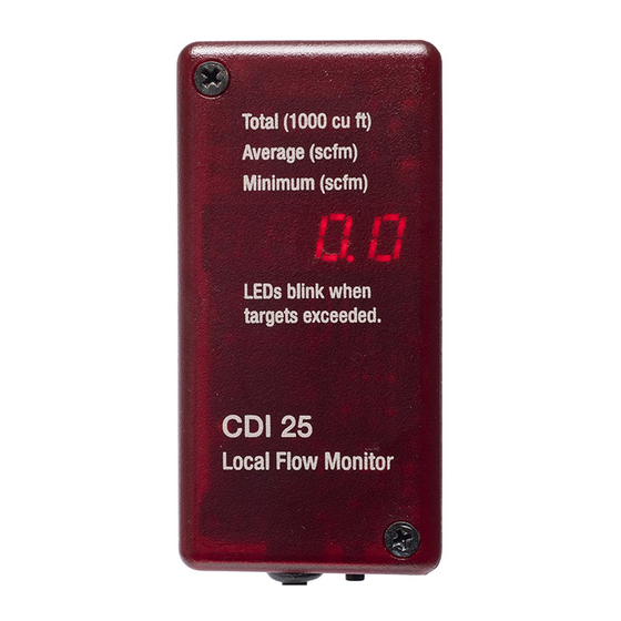
CDI 25 Flowmeter
Installation and Operating Instructions
Limitations and Cautions
CDI 25 flowmeters are not for use in hazardous areas or on pipes containing
gasses other than air or nitrogen, at pressures from atmospheric to 200 psig.
They are not designed for installation under pressure and they are not for use in
control safety applications. The temperature compensation of the meters is
suitable for use from 20 to 120°F (-7 to 49°C).
Location
For accurate and reliable readings, the meters must be installed with adequate
straight upstream pipe, and, in compressed-air applications, they must be
installed downstream of a dryer.
Select a location with a straight run of pipe upstream equal to at least twenty
times the diameter. If the meter is downstream of something that could distort or
concentrate the flow, such as a sweep elbow, a partially-closed valve, an
increase in pipe size or a hose, the run of pipe should be as long as possible;
thirty times the diameter at a minimum. Five diameters of straight downstream
pipe is sufficient, unless the meter is immediately upstream of something that
would restrict the flow, such as a valve. Select a location that meets these
requirements and also provides good visibility.
Preparing the Holes
When the holes are drilled, metal shavings will enter the pipe. Make sure that
filters or other provisions are present downstream to prevent the shavings from
damaging equipment or product or being blown out and causing injury.
Shut down the air and make sure that it will remain shut off while the meter is
being installed. Before starting to drill the holes, make sure that the air pressure
is completely bled down. Use the CDI 5200-DG drill guide. Secure the drill guide
to the pipe with a C clamp, a hose clamp or a chain clamp. If using a C clamp,
make sure that it is centered across the pipe. Drill the holes, remove the drill
guide, and remove any burrs that were formed when you drilled the holes. If the
pipe is rough near the holes, smooth it with a file.
Apply the "Holes in Pipe" decal so that it will be hidden when the meter is in place
but will be revealed when it is removed.
©
2019 CDI Meters, Inc.
10.19
Advertisement

Related Manuals for CDI Meters CDI 25 Series


Summary of Contents for CDI Meters CDI 25 Series
- Page 1 Apply the “Holes in Pipe” decal so that it will be hidden when the meter is in place but will be revealed when it is removed. © 2019 CDI Meters, Inc. 10.19...
- Page 2 If it is two, one quarter of the present value is added to three quarters of the previous filtered value, and so on, with factors available up to six. Filtered values are used in calculating minima and © 2019 CDI Meters, Inc. 10.19...
- Page 3 2 – Nm3/hr at 20 deg C m3 at 20 deg C 3 – Nm3/min at 0 deg C m3 at 0 deg C 4 – Nm3/min at 20 deg C m3 at 20 deg C © 2019 CDI Meters, Inc. 10.19...
- Page 4 CDI be liable to anyone for special, incidental or consequential damages. cdimeters CDI Meters, Inc. 3R Green Street, Woburn, MA 01801 email: support@cdimeters.com call toll free: 866-885-2462...