Table of Contents
Advertisement
Advertisement
Table of Contents

Related Manuals for Volvo Penta 31 Series


Summary of Contents for Volvo Penta 31 Series
- Page 1 INSTRUCTION BOOK 31, 32, 41, 42, 43 Series...
- Page 2 California Proposition 65 Warning Diesel engine exhaust and some of its constituents are known to the State of California to cause cancer, birth defects, and other reproduc- tive harm.
- Page 3 Welcome aboard Congratulations on your new boat and your choice of a Volvo Penta marine engine. A choice that will give you many years of boating pleasure. Your new marine engine is the result of more than 90 years experience in marine engine...
-
Page 4: Table Of Contents
Electrical system ..........41 Reverse gear ............46 Drive ..............48 Steering ..............57 Propellers .............. 60 © 1999 AB VOLVO PENTA All rights to changes or modifications reserved. Printed on enviornmentally friendly paper. (Cover: Department of transport (shipping), license 9809095) -
Page 5: Safety Precautions
Read the Instruction Manual carefully before operating or servicing the engine. If anything is unclear please contact your Volvo Penta dealer for assistance. This symbol is used in the book and on the engine to make you aware of safety information. - Page 6 Safety precautions to be taken when operating the boat Your new boat Refueling Read Instruction Manuals and other information When refueling there is always a danger of fire and supplied with your new boat. Learn to operate the explosion. Smoking is forbidden and the engine must engine, controls and other equipment safely and be switched off.
- Page 7 Most modern boats are designed in such a way that Carbon monoxide poisoning problems with backwash are extremely unusual. When a boat is moving forward backwash is caused Should a backwash problem occur do not open behind the boat. Sometimes this backwash can be so hatches or valves in the forward part of the boat.
- Page 8 Penta products are designed and constructed to workshop. minimize the risk of fire and explosion. Using non-original Volvo Penta parts can result in fire Lifting the engine or explosion on board. When lifting the engine use the lifting eyes installed on the engine (reverse gear where installed).
- Page 9 Start spray Lubrication system Never use start spray or similar agents to start an Hot oil can cause burns. Avoid skin contact with hot engine equipped with air pre-heating (glow plugs/ oil. Ensure that the lubrication system is not under starter element).
-
Page 10: Introduction
Introduction This Instruction Manual has been compiled to help you get the most from your Volvo Penta engine. It contains all the information you need in order to operate and maintain your engine safely and correctly. Please read the Instruction Manual carefully and learn how to operate the engine, controls and other equipment safely. -
Page 11: Certified Engines
Warranty and Service book. Note that AB Volvo Penta’s liability is limited to that contained in the Warranty and Service Book. Read this book as soon as you take delivery of the engine. It contains important information about warranty cards, service and maintenance which you, the owner, must be aware of, check and carry out. -
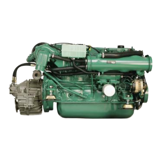
Page 12: Presentation
Presentation KAD32/DP AD31/DP AD41/DP... - Page 13 TAMD41/HS63A KAD43/DPX 3 11 9 19 KAD43/DP 16. Oil cooler, Power Steering 1. Dipstick, drive 8. Seawater filter 17. Fuel filter 9. Filling engine coolant 2. Water cooled exhaust elbow 18. Seawater pump 10. Terminal box 3. Air cleaner 11. Dipstick, engine 4.
-
Page 14: Identification Number
Identification number Your engine and transmission has identification plates with identification numbers. This information should al- ways be quoted when ordering service and replacement parts. There are probably similar plates on your boat and its equipment. Make a note of the details below, make a copy of the page and keep it so that you have a copy should the boat be stolen. -
Page 15: Instrumentation
Instrument This section contains descriptions of the instrument panels and panels available from Volvo Penta for your en- gine, with the exception of the Power Trim instrument, which is described in the section Power Trim. Note that the tachometer, oil pressure gauge, temperature gauge, charge indicator, ignition switch etc. which are shown here installed in the instrument panels can be installed in other positions on some boats. - Page 16 Control panel with ignition switch Master control position panel 1. Siren for acoustic alarm. 2. Switch for instrument lighting. 3. Alarm test/acknowledgment switch.* 4. Ignition switch*. * See description on page 15 Control panel without ignition switch Panel for Flying Bridge (alternative operating position). To start the engine from this panel the ignition key in the master panel must be in the operating position (l).
- Page 17 Warning display If the acoustic alarm sounds, one of the three warning lamps (1–3) on the instrument panel starts to flash to indicate the source of the alarm. 1. Engine coolant temperature too high. 2. Low oil pressure. 3. Generator not charging. 4.
-
Page 18: Controls
Controls The shift function and engine speed control are combined in one lever. If necessary the shift function can be easily disengaged so that only the engine speed (rpm) is affected by the lever. The control lever has an adjust- able friction brake. -
Page 19: Power Trim
Power Trim Your Volvo Penta propulsion system is equipped with a Power Trim hydraulic trim system which makes it possi- ble to adjust the angle of the drive in relation to the stern of the boat. This adjusts the boat’s trim to obtain maxi- mum comfort and fuel economy in different operating conditions. - Page 20 Lift range The lift range is used for lifting the drive to its maximum angle, however this cannot be used during normal operation of the boat. The range is used mainly for trailer transport of the boat. The Power Trim has an automatic stop which cuts off the current when the stop position is reached.
- Page 21 Trim instrument (DPX) The instrument shows the current position of the drive within the Trim range and the beginning of the Beach range. The position is indicate by the scale as follows: 0–7 = Trim range. 7–10 = Beach range. IMPORTANT! There is no automatic lockout between the Trim and Beach ranges.
-
Page 22: Starting The Engine
Starting the engine Make a habit of checking the engine and engine compartment visually before operating the boat. This will help you to quickly detect anything unusual that has or is about to happen. Also check that instruments and the warning display are indicating normal values when you have started the engine. - Page 23 3. If the engine has glow plugs installed (option) turn the key to posi- tion “II”. The indicator light comes on and the glow plugs are con- nected to pre-heat the engine. Let the glow plugs remain activated for approximately 30 seconds. 4.
-
Page 24: Operation
Operation It is important to learn how to operate the engine, controls and other equipment safely and properly before setting off on a maiden voyage. Avoid violent and unexpected changes in course and gear engagement. There is a risk that someone aboard will fall over or overboard. WARNING! A rotating propeller can cause serious injury. -
Page 25: Cruising Speed
Cruising speed Operating the engine at wide open throttle should be avoided since it is both uneconomical and uncomfortable. Volvo Penta recommends a cruising speed approximately 200 rpm lower than maximum rpm at wide open throttle. Depending on hull type, choice of propeller, load and conditions etc. -
Page 26: Power Trim
Power Trim while running The Power Trim adjusts the drive angle to the stern of the boat to obtain maximum comfort and fuel economy at different speeds, with varying loads, and in a range of wind and sea conditions. Power Trim settings and adjustment are controlled from the helm position using the controls and instruments described in the Power Trim section. - Page 27 If this is the case or if other damage has occurred to the drive it must be inspected at an au- thorized Volvo Penta workshop. If only the propeller has been dam- aged it must be replaced. Launch the boat and test drive. If there are still vibrations it must be inspected by an authorized Volvo Penta workshop.
-
Page 28: When Sailing
Trolling operation valve The reverse gear can be equipped with a trolling operation valve which makes it possible to steplessly reduce the boats lowest speed by 1-80% at engine speeds up to 1200 rpm. IMPORTANT! At higher speed the reverse gear may overheat. When sailing The propeller can cause the propeller shaft to rotate when sailing the boat. -
Page 29: Stopping The Engine
Stopping the engine The engine should be run for a few minutes at idle (in neutral) before turning it off. This will avoid boiling and even out the temperature. This is especially important if the engine has been operated at high engine speeds and loads. -
Page 30: Cold Weather Precautions
Cold weather precautions To prevent freezing damage, the seawater system must be drained and the freshwater system coolant must have sufficient antifreeze protec- tion. Refer to the section on the cooling system in “Care”. IMPORTANT! A poorly charged battery may burst as a result of freezing. -
Page 31: Maintenance Schedule
Maintenance schedule Your Volvo Penta engine and its transmission is designed for maximum service life and reliability. They are built to survive in a tough marine environment, but also to cause as little environmental impact as possible. Regular maintenance according to the following schedule is necessary if the engine and transmission are to operate without problems. -
Page 32: Maintenance
Maintenance This chapter describes how to carry out the above maintenance. Read the instructions carefully before starting work. Maintenance intervals are contained in the chapter above: Maintenance schedule. WARNING! Read the safety precautions for maintenance and service in the chapter: Safety Precautions, before starting work. - Page 33 Exhaust system. Check The exhaust system in the drive installations must be checked every year for corrosion damage between hose (1) and the pipe (2). WARNING! Risk of water penetration. Checking the exhaust system should be carried out with the boat on land. If there is heavy corrosion the pipe should be re- paired or replaced with a new one.
- Page 34 2. Generator belt Undo the generator mounting bolts (1) and (2). Tighten belt using the adjuster screw (3) so the belt can be depressed approximately 10 mm between the belt pulleys at (B). Tighten bolts (1) and (2). 3. Compressor belt (32, 43) Remove the belt cover.
-
Page 35: Lubrication System
Lubrication system IMPORTANT! With a new or reconditioned engine, the oil and oil filters must be changed after 20–50 hours of operation. After that they should be changed every 100 operating hours or at least once a year. Use only the recommended grades of oil: See the chapter “Technical Data”. -
Page 36: Cooling System
If there is a risk for freezing at any time of year, the engine coolant system must be filled with a mixture of 50% Volvo Penta antifreeze and 50% clean water (as neutral pH as possible). This mixture prevents corrosion and protects against freezing down to ap- prox. - Page 37 Coolant. Changing The corrosion-proofing additives become less effec- tive with time and the coolant must be changed. If the freshwater system is filled with antifreeze mix- ture it must be changed every other year. If the sys- tem is filled with anti-corrosion agent mixture it must be changed every year.
- Page 38 Seawater system. Draining To prevent freezing damage the seawater system must be drained in cold weather where there is a risk of frost. WARNING! If the boat is left in the water, the seawater intake to the engine must be turned off with a seawater cock (non-standard equip- ment) or other method before draining the en- gine.
- Page 39 Seawater system. Cleaning and inhibiting To prevent the build up of deposits and salt crystals in the seawater system it must be flushed with fresh- water. When the boat is laid up it must also be inhibit- WARNING! Risk of water penetration. Clean- ing and inhibiting the seawater system should be carried out with the boat on land.
- Page 40 Impeller. Checking/Replacing WARNING! Risk for water penetration. If the boat is in the water the following measures should be carried out before starting work: Reverse gear: Close the sea cock. Remove the cover from the seawater pump and re- move the impeller (1). If there are cracks or other defects the impeller must be replaced.
-
Page 41: Fuel System
Fuel system All work on the engine injection pump or injectors must be carried out at an authorized workshop. Use only the recommended grade of fuel: See the chapter “Technical Data”. WARNING! Fire risk. When carrying out work on the fuel system make sure the engine is cold. A fuel spill onto a hot surface or an electrical component can cause a fire. - Page 42 Fuel filter. Replacement Clean the filter mounting. To avoid fuel spills put a plastic bag over the filter before it is unscrewed. Un- screw the filter. Moisten the filter rubber gasket with a little oil. Screw on the new filter by hand until it is in contact with the mating surface.
-
Page 43: Electrical System
IMPORTANT! Always carry extra fuses on board. Electrical connections Also check that all electrical connections are dry and free of oxidation and that there are no loose connec- tions. If necessary, spray these connections with a water-repellent spray (Volvo Penta Universal oil). - Page 44 Battery. Maintenance WARNING! Risk of fire and explosion. Never allow an open flame or electric sparks near the battery or batteries. WARNING! Never mix up battery positive and negative terminals. This may cause sparks and an explosion. WARNING! The battery electrolyte contains ex- tremely corrosive sulfuric acid.
- Page 45 Battery. Charging WARNING! Danger of explosion! The batteries give off hydrogen gas during charging which when mixed with air can form an explosive gas –oxyhydrogen A short-circuit, naked flame or spark can cause a large explosion. Ensure that the ventilation is good. WARNING! The battery electrolyte contains ex- tremely corrosive sulfuric acid.
- Page 46 Electrical installations Leakage current from the electrical system can be caused by incorrect installation of electrical equip- ment. Leakage current can knock out the galvanic protection of components such as the drive, propel- ler, propeller shaft, rudder stock and keel and cause damage by electrolytic corrosion.
- Page 47 All equipment connected to the auxiliary battery should have separate switches. To simultaneously charge two independent bat- tery circuits, fit a Volvo Penta charge distributor (accessory) to the regular generator.
-
Page 48: Reverse Gear
The reverse gear lubrication system has an oil filter and oil cooler. IMPORTANT! Volvo Penta recommends the installation of a seawater filter to guarantee the proper cool- ant water flow to the engine and reverse gear. Contaminants in the seawater will otherwise foul the re- verse gear radiator and other cooling system components. - Page 49 Propeller shaft seal If the boat has a Volvo Penta shaft the shaft seal must be vented and lubricated directly after launch- ing. Vent the bushing by pressing it together while press- ing down on the shaft until water appears. Then press in approx.
-
Page 50: Drive
Drive DP, DPX Your drive is protected against galvanic corrosion. This protection consists of five layers of paint, sacrificial anodes and ground braids. The ground braids maintain a connection between the different components of the drive. A broken connection can result in the rapid corrosion of an individual component even though the pro- tection is otherwise effective. - Page 51 Undo the two screws holding the anode (2). Remove the anode and the support plate under the anode. Clean the mating surface. Reinstall support plate and the new anode. IMPORTANT! DP drives equipped with stain- less steel propellers must be equipped with two sacrificial anodes on the shield.
- Page 52 Remove the plug on the gear hous- ing and let the oil run out. If oil is discolored, contact an authorized Volvo Penta workshop. Reinstall plug and O ring. Always replace a damaged O ring with a new one.
- Page 53 The drive may need to be re- moved from the support fork to replace the bellows. Removal of the drive requires special knowledge and tools. If in doubt contact your Volvo Penta work- shop for assistance. WARNING! Never work on the drive bellows or hydraulic system without locking the drive in its raised position so that it cannot fall down.
- Page 54 DP: If the drive has been removed the steering rack and drive controlling the trim sensor may have come out of position. Turn the cog until the notched tooth is visible. Install the steering rack so that the first cog position meshes with the marked tooth.
- Page 55 Active Corrosion-Protection Most boats are equipped with a Volvo Penta Active Corrosion Protection System as standard equip- ment. The system greatly improves the protection and life of the drive unit from corrosion. If your boat does not have this system as standard you can buy it as an accessory.
- Page 56 Oil level. Check Trim the drive to it's normal running position. Remove the dipstick (A) and check the oil level covers the en- tire marked area. Add oil if required through the dip- stick hole. If oil level is low, add only enough lubricant to bring the oil level within the full range of dipstick.
- Page 57 WARNING! Removal of the drive requires spe- cial knowledge and tools. A falling drive can cause serious personalinjury. Please contact your nearest authorized Volvo Penta dealer for assistance. IMPORTANT! Failure to lubricate the gimbal bearing and universal joints each year will re- sult in damage to the pivot housing and drive unit.
- Page 58 Because of the special tools required, engine alignment must be performed by a Volvo Penta dealer. IMPORTANT Failure to check engine alignment could result in premature failure of engine coupler, universal joints, and gimbal...
-
Page 59: Steering
Steering The DP drive is equipped with power-assisted mechanical steering. The DPX drive is equipped with the Xact™ fully hydraulic power steering system. DP power steering pump. Oil level Turn the filler cap counterclockwise and remove. Check the oil level is between the MAX and MIN markings on the dipstick. - Page 60 DPX Hydraulic pump Oil level Check with the engine(s) idling. The level should be between MAX and MIN markings on the dipstick. NOTE! The level is slightly higher with the engine stopped. Fill with ATF. For ATF grade, see Technical data.
- Page 61 Faulty routing or dirt in the hydraulic sys- tem can negatively affect steering, and at worst steering can be lost altogether. Please contact your nearest authorized Volvo Penta workshop for assistance. DPX Parallel strut. Checking The parallel strut (twin and triple installation) is a vital safety component.
-
Page 62: Propellers
3. Lubricate both propeller hubs. Use Volvo Penta grease 828250-1. 8. Screw on the propeller nut cone and tighten hard. Install the center screw and washer and tighten 4. - Page 63 2. Use the tool supplied when removing and installing nut. Use a 30 mm socket and tighten to 25–35 Nm propellers. (2.5–3.5 kpm) 3. Lubricate both propeller hubs. Use Volvo Penta 7. Screw in the lock screw and tighten to 70–80 Nm grease 828250-1. (7–8 kpm).
- Page 64 Under these conditions stop the engine and check the propeller for damage. If the propeller appears dama- ged, have it checked by your local Volvo Penta dealer. Always carry a spare propeller and replace the damaged propeller as soon as possible.
- Page 65 Removal Installation Coat the full length of both propeller shafts with WARNING! Ignition switch must be OFF. Volvo Penta propeller shaft grease. Place remote control in the FORWARD position to Place remote control in the FORWARD position lock propeller shafts.
-
Page 66: Laying Up/Launching
Laying up/Launching Before taking the boat out of the water for winter/out-of-season storage have an authorized Volvo Penta workshop inspect the engine and other equipment. Have any necessary repairs or service work carried out so that your boat is in top condition for the new season. -
Page 67: Bringing Out Of Storage
Bringing out of storage Connect the fully charged batteries. Check oil level in the engine and drive/reverse Paint the drive and hull: See next page. gear. Top up if necessary. If there is inhibiting oil in the system drain and fill with new oil, Check the sacrificial anode on the drive. -
Page 68: Painting The Drive And Underwater Hull
Let the paint dry. A fur- ther two coats of Volvo Penta anti-fouling primer should then be applied. Let them dry. A further two coats of Volvo Penta anti-fouling should then be ap- plied. IMPORTANT! The sacrificial anodes on the drive must not be painted or treated with Teflon. -
Page 69: Fault-Tracing/Diagnostics
Fault-tracing Problem Probable cause Starter motor not turning (or slow) 1, 2, 3 Engine does not start 4, 5, 6, 7 Engine starts but stops again 6, 7 Engine difficult to start 4, 5, 6, 7 Engine does not reach correct speed at wide open throttle (WOT) 5, 6, 7, 8, 9, 10, 11, 15, 18, 19, 20, 21 Engine knocks 4, 5, 6, 7... -
Page 70: Technical Data
Technical Data General Engine designation ........AD31L/P AD41P KAD43P KAD32P TAMD41H/M/P KAMD43P TAMD31L/M/P TMD41L TAMD42A/WJ* TMD31L Idling speed, rpm ......... 675–725 625–725 625–675 Cylinder displacement, dm ......2.39 3.59 3.59 Injection order ..........1-3-4-2 1-5-3-6-2-4 1-5-3-6-2-4 Rotational direction, viewed from in front ..Clockwise Clockwise Clockwise... - Page 71 Oil capacity (without oil cooler)....4.0 litres Hydraulic steering (Volvo Penta) Oil grade ............Volvo Penta P/N 1141640-1, Shell Aero 4, Texaco HO15 Esso Univis N15, Chevron Aviation Fluid A, Mobil Aero HFA Hydraulic steering (DPX) Oil grade ............
- Page 72 Notes ________________________________________________ ________________________________________________ ________________________________________________ ________________________________________________ ________________________________________________ ________________________________________________ ________________________________________________ ________________________________________________ ________________________________________________ ________________________________________________ ________________________________________________ ________________________________________________ ________________________________________________ ________________________________________________ ________________________________________________ ________________________________________________ ________________________________________________ ________________________________________________ ________________________________________________ ________________________________________________ ________________________________________________ ________________________________________________...
- Page 74 AB Volvo Penta SE-405 08 Göteborg, Sweden www.volvopenta.com...
Need help?
Do you have a question about the 31 Series and is the answer not in the manual?
Questions and answers