Table of Contents
Advertisement
Quick Links
SPLIT SYSTEM
MODELS
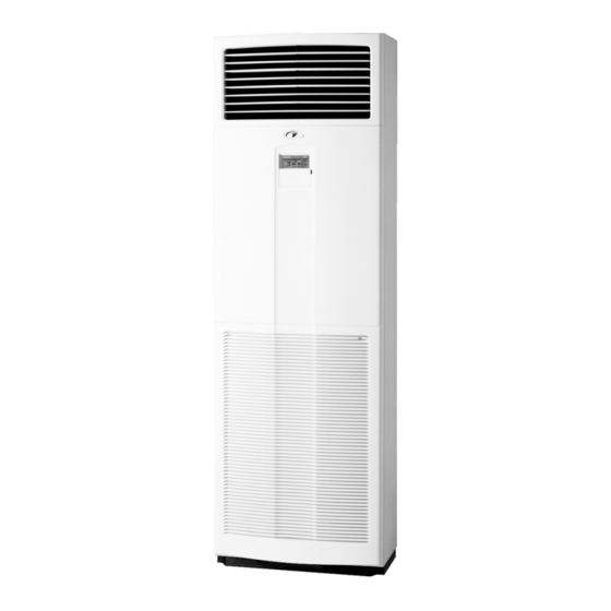
(Floor standing type)
FVQ71BV1B
FVQ100BV1B
FVQ125BV1B
READ THESE INSTRUCTIONS CAREFULLY BEFORE INSTALLATION.
KEEP THIS MANUAL IN A HANDY PLACE FOR FUTURE REFERENCE.
LESEN SIE DIESE ANWEISUNGEN VOR DER INSTALLATION SORGFÄLTIG DURCH.
BEWAHREN SIE DIESE ANLEITUNG FÜR SPÄTERE BEZUGNAHME GRIFFBEREIT AUF.
LIRE SOIGNEUSEMENT CES INSTRUCTIONS AVANT L'INSTALLATION.
CONSERVER CE MANUEL A PORTEE DE MAIN POUR REFERENCE ULTERIEURE.
LEA CUIDADOSAMENTE ESTAS INSTRUCCIONES ANTES DE INSTALAR.
GUARDE ESTE MANUAL EN UN LUGAR A MANO PARA LEER EN CASO DE TENER
ALGUNA DUDA.
PRIMA DELL'INSTALLAZIONE LEGGERE ATTENTAMENTE QUESTE ISTRUZIONI.
TENERE QUESTO MANUALE A PORTATA DI MANO PER RIFERIMENTI FUTURI.
ÄΙΑΒΑΣΤΕ ΠΡΟΣΕΚΤΙΚΑ ΑΥΤΕΣ ΤΙΣ ΟÄΗΓΙΕΣ ΠΡΙΝ ΑΠΟ ΤΗΝ ΕΓΚΑΤΑΣΤΑΣΗ ΕΧΕΤΕ ΑΥΤΟ
ΤΟ ΕΓΧΕΙΡΙÄΙΟ ΕΥΚΑΙΡΟ ΓΙΑ ΝΑ ΤΟ ΣΥΜΒΟΥΛΕΥΕΣΤΕ ΣΤΟ ΜΕΛΛΟΝ.
LEES DEZE INSTRUCTIES ZORGVULDIG DOOR VOOR INSTALLATIE. BEWAAR DEZE HAN-
DLEINDING WAAR U HEM KUNT TERUGVINDEN VOOR LATERE NASLAG.
LEIA COM ATENÇÃO ESTAS INSTRUÇÕES ANTES DE REALIZAR A INSTALAÇÃO.
MANTENHA ESTE MANUAL AO SEU ALCANCE PARA FUTURAS CONSULTAS.
ПЕРЕД НАЧАЛОМ МОНТАЖА ВНИМАТЕЛЬНО ОЗНАКОМЬТЕСЬ С ДАННЫМИ
ИНСТРУКЦИЯМИ. СОХРАНИТЕ ДАННОЕ РУКОВОДСТВО В МЕСТЕ, УДОБНОМ ДЛЯ
ОБРАЩЕНИЯ В БУДУЩЕМ.
MONTAJDAN ÖNCE BU TALÝMATLARI DÝKKATLÝ BÝR BÝÇÝMDE OKUYUN.
GELECEKTE BAÞVURMAK ÜZERE BU ELKÝTABINI KOLAY ULAÞABÝLECEÐÝNÝZ BÝR YERDE
MUHAFAZA EDÝN.
INSTALLATION MANUAL
Air Conditioners
English
Deutsch
Français
Español
Italiano
ëëçíéêÜ
Nederlands
Portugues
óññêèé
Advertisement
Table of Contents

Related Manuals for Daikin FVQ71BV


Summary of Contents for Daikin FVQ71BV
- Page 1 INSTALLATION MANUAL English SPLIT SYSTEM Air Conditioners Deutsch MODELS Français (Floor standing type) FVQ71BV1B Español FVQ100BV1B FVQ125BV1B Italiano READ THESE INSTRUCTIONS CAREFULLY BEFORE INSTALLATION. KEEP THIS MANUAL IN A HANDY PLACE FOR FUTURE REFERENCE. ëëçíéêÜ LESEN SIE DIESE ANWEISUNGEN VOR DER INSTALLATION SORGFÄLTIG DURCH. BEWAHREN SIE DIESE ANLEITUNG FÜR SPÄTERE BEZUGNAHME GRIFFBEREIT AUF.
- Page 2 3P104327-1E...
-
Page 3: Table Of Contents
FVQ71BV1B FVQ100BV1B SPLIT SYSTEM Air Conditioner Installation manual FVQ125BV1B CONTENTS 1. SAFETY PRECAUTIONS..................1 2. BEFORE INSTALLATION ..................3 3. SELECTING INSTALLATION SITE..............5 4. INDOOR UNIT INSTALLATION ................5 5. REFRIGERANT PIPING WORK................6 6. DRAIN PIPING WORK ..................9 7. SEPARATE INSTALLATION OF THE CONTROL PANEL ........10 8. - Page 4 • Make sure that all wiring is secured, the specified wires are used, and that there is no strain on the terminal connections or wires. Improper connections or securing of wires may result in abnormal heat build-up or fire. • When wiring the power supply and connecting the wiring between the indoor and outdoor units, position the wires so that the terminal box lid can be securely fastened.
-
Page 5: Before Installation
2. BEFORE INSTALLATION • The accessories needed for installation must be retained in your custody until the installation work is completed. Do not discard them! • Decide upon a line of transport. • When transporting by hanging the unit, use a sling of soft material as shown below. (1) Horizontal hanging (2) Vertical hanging Sling... - Page 6 FOR THE FOLLOWING ITEMS, TAKE SPECIAL CARE DURING CONSTRUCTION AND CHECK AFTER INSTALLATION IS FINISHED. 1. Items to be checked after completion of work Items to be checked If not properly done, what is likely to occur Check Are the indoor and outdoor unit fixed The unit may drop, vibrate or make noise.
-
Page 7: Selecting Installation Site
3. SELECTING INSTALLATION SITE Select an installation site where the following conditions are satisfied after obtaining your customer’s approval. • Where optimum air distribution can be ensured. • Where nothing blocks the air inlet and outlet, and where sufficient clearance for maintenance and service can be ensured. -
Page 8: Refrigerant Piping Work
2. In case of normal installation site. Loosen the fixed screw and remove the bracket for installation (1) tentatively attached to the top panel. Fix the bracket with the attached screws (12) to the top panel as shown in the figure. Then fix the indoor unit to the wall surface with wood screws (field supply). - Page 9 CAUTION • Use a pipe cutter and flare suitable for the type of refrigerant. • Apply ester oil or ether oil around the flare section before connecting. • To prevent dust, moisture or other foreign matter from infiltrating the tube, either pinch the end or cover it with tape.
- Page 10 1. How to rig refrigerant piping. • Detach the pipe retainer. 〈 In the case of left or right piping 〉 1. Open the holes on the right (left) side panel. (Refer to Fig. 3) 2. Pass refrigerant pipes, drain pipes, and unit wiring through the hole on the side panel. Fig.
-
Page 11: Drain Piping Work
6. DRAIN PIPING WORK 1. Rig the drain piping. Rig the drain line to ensure proper drainage. Also, observe the following to prevent leaks. Drain hose inside the unit Fan housing Bottom frame Liquid pipe Anchor hose here. Drain pipes (Procure in field.) Gas pipe Vinyl tube (pipe size I.D. -
Page 12: Separate Installation Of The Control Panel
7. SEPARATE INSTALLATION OF THE CONTROL PANEL • For this unit, remote controller (operation part) attached to the control panel can be installed separately by using the field supplied remote controller cord. Refer to section of ELECTRIC WIRING WORK (p. 12) for specifications of remote controller cord. 1. - Page 13 4. Connect the remote controller Terminal box lid Remote controller wiring (field supplied) to the terminal board remote controller terminal board and lead the wiring out of the unit as shown below. • Lock the remote controller wiring to the piping guide.
-
Page 14: Electric Wiring Work
8. ELECTRIC WIRING WORK • All field supplied parts and materials and electric works must conform to local codes. • Use copper wire only. • For electric wiring work, refer also to “WIRING DIAGRAM” attached to the unit body. • For remote controller wiring details, refer to the installation manual attached to the remote controller. •... -
Page 15: Wiring Example
• In order to prevent the intrusion of small creatures, seal the wiring outlet with putty or heat insulating material (field supply). (If small creatures, such as insects, intrude into the unit, the creatures may cause short-circuiting in the terminal box.) CAUTION •... - Page 16 Group control Main power supply Main power supply Main power supply Main switch Main switch Main switch Fuse Fuse Fuse Outdoor unit Outdoor unit Outdoor unit 1 2 3 1 2 3 1 2 3 Control Control Control Panel Panel Panel (NOTE 3) (NOTE 3)
-
Page 17: Installation Of Air Intake Grille
2. Turn the MAIN/SUB CHANGEOVER SWITCH on one of the two remote controller PC boards to “S”. (Leave the switch to the other remote controller set to “M”.) (Factory setting) Remote controller PC board Only one remote controller needs to be charged. 10. -
Page 18: Field Setting
11. FIELD SETTING Field setting 〈 〉 Field setting must be made from the remote controller in accordance with the installation conditions. • Setting can be made by changing the “Mode No.”, “FIRST CODE NO.”, and “SECOND CODE NO.”. • Refer to the following procedure for Field setting. 〈... -
Page 19: Test Operation
Table 2 Filter cleaning period FIRST SECOND Setting Mode No. (long life type) CODE NO. CODE NO. Air filter Approx. 2500 hrs. contamination-light 10 (20) Air filter Approx. 1250 hrs. contamination-heavy 2. Setting indoor unit number of simultaneous operation system •... - Page 20 2. HOW TO DIAGNOSE FOR PROBLEMS With the power on. Troubles can be monitored on the control panel. ■ Trouble shooting with the display on the liquid crystal display control panel. 1 With the control panel. (NOTE 1) When the operation stops due to trouble, operation lamp flashed, and “ ”...
- Page 21 Compressor motor lock malfunction (outdoor unit) Outdoor fan motor lock malfunction Outdoor fan instantaneous overcurrent malfunction (outdoor unit) Electronic expansion valve faulty (outdoor unit) Discharge pipe temperature abnormal (outdoor unit) High pressure switch faulty (outdoor unit) Outdoor motor position signal malfunction (outdoor unit) Outdoor air thermistor faulty (outdoor unit) The air conditioner comes to a stop due to an error depending on the model or operating conditions.
-
Page 22: Wiring Diagram
Malfunction in transmission between main and sub remote controllers. (Malfunction in sub remote controller.) Miss setting for multi system Error in multi-system settings for simultaneous ON/OFF operation. Central control address overlapping Transmission failure in accessory equipment 13. WIRING DIAGRAM (Refer to Fig. 6) TO OUTDOOR UNIT CONTROL PANEL TERMINAL BOX... - Page 23 Fig. 6 English...
- Page 24 3PA60136-8Y EM07A043A (0802) HT...
Need help?
Do you have a question about the FVQ71BV and is the answer not in the manual?
Questions and answers