Table of Contents
Advertisement
Quick Links
AW07A Instruction Manual
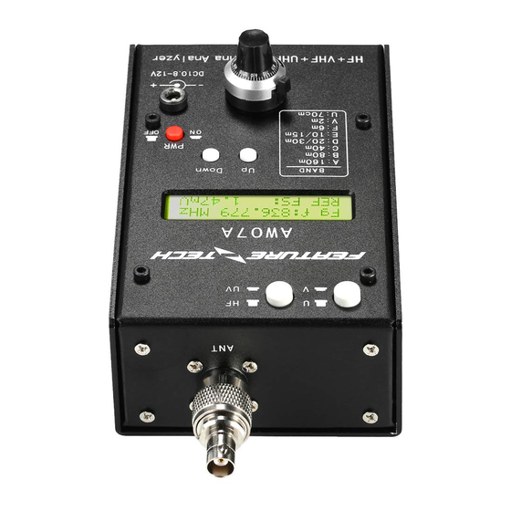
AW07A HF/VHF/UHF Antenna Analyzer
INTRODUCTION
AW07A antenna analyzer is a compact battery powered RF impedance analyzer. It can test the SWR
status of your antenna, measure the impedance and reactance component and help you to solve antenna
problems. This unit combines six basic parts: a variable oscillator, frequency counter, independent oscillator,
50 ohm RF bridge detector, an A-D converter, and microcontroller. This compact product was built to feed the
need for the solid construction and field test. The operating frequency range of this unit goes from HF, and
extends up to 490MHz. It is specially designed for analyzing 50ohm antenna system. It measures RF
impedances from a few ohms to several hundred ohms. The AW07A is also an L/C meter, measuring the
values of capacitors and inductors. Additionally, it could be a non-precision signal source and frequency
counter. With a built-in RF strength meter, it tests the RF field strength near your antenna system, and it's
very useful when you need to know the RF interference status around your station. The AW07A also
functions as a non-precision signal source and frequency counter. The operating frequency range of this unit
extends from 1.5 to 71 MHz in six overlapping bands, and includes SWR measurements on 85-185MHz ,
300-490 MHz.
1
Advertisement
Table of Contents

Related Manuals for Feature tech AW07A

Summary of Contents for Feature tech AW07A
- Page 1 490MHz. It is specially designed for analyzing 50ohm antenna system. It measures RF impedances from a few ohms to several hundred ohms. The AW07A is also an L/C meter, measuring the values of capacitors and inductors. Additionally, it could be a non-precision signal source and frequency counter.
- Page 2 If the message is cleared, you need to power off the unit and re-power on again for the operation. If you do nothing, AW07A will entry next Menu (SWR Analyzer or Frequency Counter) in 1 Sec. Press “Down” button to Frequency Counter Mode, while pressing “Up”...
- Page 3 BAND SELECTING: The 2 switches on the left-upper side of the analyzer are the switches to change band ranges. By pressing the two switches up and down, the frequency ranges change from HF to UHF. EXAMPLES: SWITCH TO UHF: 1. POWER ON 2.
- Page 4 SWITCH TO HF: 1. POWER ON 2. Press the button “Up” to Ant Mode 3. Keep the HF/UV switch UP 4. Press the Up/Down button on the center position of your analyzer to change to different HF bands (BAND A to F) Notes: Frequency range in HF bands (BAND A to F), a small frequency overlap may be possible, please see the following: A: 1.5-2.7 MHz...
- Page 5 2. Press “Up” for the backlight on or off 3. Keep the “HF/UV” switch UP. 4. Press “Down” to enter the Frequency Counter Mode 5. Connect the signal source to your AW07A Please see the picture below as an example.
- Page 6 Notes: The Frequency Range of AW07A in Frequency Mode is 1-500MHz.The “Frequency Mode” of AW07A has two time gate, they are expressed by “Fg” and “Sg”. “Fg” is the Fast Gate, while “Sg” represents Slow Gate. In Fast Gate Mode, the displayed frequency is only 6 digits, counted in MHz.
- Page 7 After the cover mounting screws are removed, remove the entire back cover. Battery box is accessed by removing the AW07A’s cover. Place 8× 1.5V (not 1.2V) AA size batteries into the battery box. DO NOT use external power supply when replacing batteries.
Need help?
Do you have a question about the AW07A and is the answer not in the manual?
Questions and answers