Table of Contents
Advertisement
Quick Links
Intel
mini-ITX Motherboard
®
USER'S MANUAL
Intel
*
The WEEE marking on the product indicates this product must not be disposed of with
user's other household waste and must be handed over to a designated collection point
for the recycling of waste electrical and electronic equipment!!
*
The WEEE marking applies only in European Union's member states.
MNNM1PI
mini-ITX Motherboard
®
Rev. 1001
Advertisement
Table of Contents

Related Manuals for Gigabyte MNNM1PI


Summary of Contents for Gigabyte MNNM1PI
- Page 1 MNNM1PI Intel mini-ITX Motherboard ® USER’S MANUAL Intel mini-ITX Motherboard ® Rev. 1001 The WEEE marking on the product indicates this product must not be disposed of with user's other household waste and must be handed over to a designated collection point for the recycling of waste electrical and electronic equipment!! The WEEE marking applies only in European Union's member states.
- Page 2 Gigabyte's prior written permission. Specifications and features are subject to change without prior notice. Product Manual Classification In order to assist in the use of this product, Gigabyte has categorized the user manual in the following: For detailed product information and specifications, please carefully read the "Product User Manual".
-
Page 3: Table Of Contents
MNNM1PI Motherboard Table of Content Item Checklist ..................4 Chapter 1 Introduction ................5 1-1Considerations Prior to Installation ............5 1.2 Features Summary ................6 1.3 Motherboard Components ..............8 Chapter 2 Hardware Installation Process ..........9 2-1: Installing Memory Module ..............9 2-2: Connect ribbon cables, cabinet wires, and power supply .... -
Page 4: Item Checklist
Introduction Item Checklist The MNNM1PI motherboard I/O Shield Kit CD for motherboard driver & utility Power cable x 1 B4P/S4P Cable x 1 Optional Power Adapter x 1 * The items listed above are for reference only, and are subject to change without notice. -
Page 5: Chapter 1 Introduction
2. Damage as a result of violating the conditions recommended in the user manual. 3. Damage due to improper installation. 4. Damage due to use of uncertified components. 5. Damage due to use exceeding the permitted parameters. 6. Product determined to be an unofficial Gigabyte product. -
Page 6: Features Summary
Introduction Features Summary Form Factor 170mm x 170mm Mini ITX form factor, 8 layers PCB. Supports single Intel D410 processor ® Supports DMI x4 Chipset Intel NM10 ® Memory 2 x DDR2 DIMM socket Supports up to 4GB 800 memory ... - Page 7 MNNM1PI Motherboard CPU shutdown when overheat On-Board LAN Realtek 8111DL GbE LAN controller Supports WOL, PXE BIOS AMI BIOS on 8Mb SPI Flash ROM Additional Features External Modem wake up Supports S1, S3, S4, S5 under Windows Operating System ...
-
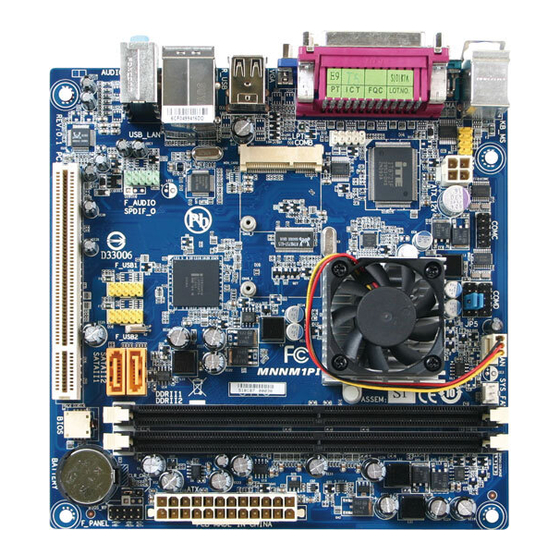
Page 8: 1.3 Motherboard Components
Introduction 1.3 Motherboard Components COMA ALC662 COMB MIN_CARD F_AUDIO ATX_12V 8111DL Intel F_USB1 NM10 F_USB2 DDRII1 BIOS DDRII2 BATTERY F_PANEL... -
Page 9: Chapter 2 Hardware Installation Process
Hardware Installation Process Chapter 2 Hardware Installation Process 2-1: Installing Memory Module Before installing the memory modules, please comply with the following conditions: 1. Please make sure that the memory is supported by the motherboard. It is recommended to use the memory with similar capacity, specifications and brand. 2. -
Page 10: 2-2: Connect Ribbon Cables, Cabinet Wires, And Power Supply
MNNM1PI Motherboard 2-2: Connect ribbon cables, cabinet wires, and power supply 2-2-1 : I/O Back Panel Introduction... - Page 11 Hardware Installation Process PS/2 Keyboard and PS/2 Mouse Connector To install a PS/2 port keyboard and mouse, plug the mouse to the upper port (green) and the keyboard to the lower port (purple). Parallel Port/ COM Port/ VGA Port This connector supports 1 standard COM port and 1 Parallel port. Device like printer can be connected to Parallel port ;...
- Page 12 MNNM1PI Motherboard LAN LED Description LED2 (Green/Orange) LED1 (Yellow) Name Color Condition Description LED1 Green LAN Link / no Access Green BLINK LAN Access Idle LED2 10Mbps connection Port identification with 10 Mbps connection Green 100Mbps connection Green BLINK Port identification with 100Mbps connection...
-
Page 13: 2-3: Connectors Introduction & Jumper Setting
Connector Introduction 2-3: Connectors Introduction & Jumper Setting 1. ATX 9. F_USB1 (Fornt USB cable connector) 2. ATX_12V 10. F_USB2 (Fornt USB cable connector) 3. SATAII1 (SATA cable connector) 11. F_AUDIO 4. SATAII2 (SATA cable connector) 12. DIO (Digtal I/O connector) 5. - Page 14 Connector Introduction 1/2/3 ) ATX1/ATX_12V (24-pin/4-pin ATX power connectors) With the use of the power connector, the power supply can supply enough stable power to all the components on the motherboard. Before connecting the power connector, please make sure that all components and devices are properly installed.
- Page 15 MNNM1PI Motherboard Pin No. Definition Pin No. Definition 3.3V 3.3V -12V 3.3V PS_ON(soft On/Off) Power Good 5V SB(stand by +5V) +12V +12V(Only for 24-pin ATX) +5V (Only for 24-pin ATX) 3.3V(Only for 24-pin ATX) GND(Only for 24-pin ATX) 3/ 4 ) SATAII 1/2 (Serial ATA cable connectors) SATA 3Gb/s can provide up to 300MB/s stransfer rate.
- Page 16 MNNM1PI Motherboard 5/6/7 ) COMB/COMC/COMD (Serial cable connectors) COMC COMB COMD COMB COMC COMD 9 10 9 10 Pin No. Definition Pin No. Definition Pin No. Definition NDCDB- NDCD3- NDCD4- NRXDB NRXD3 NRXD4 NTXDB- NTXD3- NTXD4- NDTRB- NDTR3- NDTR4- NDSRB-...
- Page 17 MNNM1PI Motherboard 8 ) JP5 (Power COM selection jumper) Pin No. Definition IO_12V IO_12V COM_NRIC COM_NRID 9 10 IO_VCC IO_VCC COM_NRIC COM_NRID NRIC- NRID- +12V Default COM_C Close Close Close Close PIN 9 7_9 pin 5_7 pin 3_5 pin 1_3 pin...
- Page 18 MNNM1PI Motherboard 9/10 ) F_USB1/F_USB2 (Front USB cable connectors) Be careful with the polarity of the front USB connector. Check the pin assignment carefully while you connect the front USB cable, incorrect connection between the cable and connector will make the device unable to work or even damage it.
- Page 19 Connector Introduction 12 ) DIO (Digtal I/O connector) Pin No. Definition VCC3 VCC3 VCC3 VCC3 ATX_3VSB ATX_3VSB ATX_3VSB 13/14 ) CPU_FAN/SYS_FAN (CPU fan/System fan cable connectors) The cooler fan power connector supplies a +12V power voltage via a 3-pin/4-pin(CPU_FAN) power connector and possesses a foolproof connection design. Most coolers are designed with color-coded power connector wires.
- Page 20 Connector Introduction 15 ) F_Panel (2X5 Pins Front Panel connector) Please connect the power LED, PC speaker, reset switch and power switch of your chassis front panel to the F_PANEL connector according to the pin assignment above. Pin No. Signal Name Description Hard Disk LED Signal anode (+) MSG+...
- Page 21 MNNM1PI Motherboard 16 ) BATTERY If you want to erase CMOS... 1.Turn OFF the computer and unplug the power cord. 2.Remove the battery, wait for 30 second. 3.Re-install the battery. 4.Plug the power cord and turn ON the computer. CAUTION ...
-
Page 22: Chapter 3 Bios Setup
MNNM1PI Motherboard Chapter 3 BIOS Setup BIOS (Basic Input and Output System) includes a CMOS SETUP utility which allows user to configure required settings or to activate certain system features. The CMOS SETUP saves the configuration in the CMOS SRAM of the motherboard. -
Page 23: Getting Help
MNNM1PI Motherboard GETTING HELP Main Menu The on-line description of the highlighted setup function is displayed at the bottom of the screen. Status Page Setup Menu / Option Page Setup Menu Press F1 to pop up a small help window that describes the appropriate keys to use and the possible selections for the highlighted item. -
Page 24: Main
MNNM1PI Motherboard Main Once you enter AMI BIOS Setup Utility, the Main Menu will appear on the screen. Use arrow keys to select among the items and press <Enter> to accept or enter the sub-menu. BIOS SETUP UTILITY Main Advanced... -
Page 25: Advanced
MNNM1PI Motherboard Advanced About This Section: Advanced With this section, allowing user to configure your system for advanced operation. The advanced menu includes sub-menu of CPU Configuration, IDE Configuration, Floppy Configuration, Super IO Configuration, Hardware Health Configuration, ACPI Configuration, MPS Configuration, and USB Configuration. -
Page 26: Cpu Configuration
MNNM1PI Motherboard CPU Configuration BIOS SETUP UTILITY Main Advanced PCIPnP Boot Security Chipset Exit CPU Configuration Module Version: 3F.15 Manufacturer: Intel Intel (R) Atom(TM) CPU K410 @ 1.66GHz Frequency :1.66GHz :666MHz Cache L1 :24KB Cache L2 :512KB Ratio Actual Vaule : 10... -
Page 27: Ide Configuration
MNNM1PI Motherboard IDE Configuration BIOS SETUP UTILITY Main Advanced PCIPnP Boot Security Chipset Exit IDE Configuration Configure SATA as [IDE] Primary IDE Master Secondary IDE Master IDE Detect Time Out (Sec) [35] Select Screen ... - Page 28 MNNM1PI Motherboard Auto: Set parameters automatically. (Default setting) CD-ROM: Use for ATAPI CD-ROM drives or double click [Auto] to set all HDD parameters automatically. ARMD: Use ARMD drive is installed here. LBA/Large Mode Configure the device type in the specific IDE channel support LBA Mode.
- Page 29 MNNM1PI Motherboard 32Bit Data Transfer Configure the 32Bit Data Transfer rate. Enabled: Enable 32Bit Data Transfer rate. Disabled: 32Bit Data Transfer rate. Auto: Auto configuration. (Default setting) IDE Detect Time Out (Sec) Configure the IDE star unit command timeout. Desfault setting is 35 seconds.
-
Page 30: Super Io Configuration
MNNM1PI Motherboard Super IO Configuration BIOS SETUP UTILITY Main Advanced PCIPnP Boot Security Chipset Exit Configure ITE8721 Super IO Chipset Serial Port1 Address [3F8/IRQ4] Serial Port2 Address [2F8/IRQ3] Parallel Port Address [378] Parallel Port Mode [Normal] Parallel Port IRQ [IRQ7]... -
Page 31: Parallel Port Address
MNNM1PI Motherboard Parallel Port Address Enable parallel port and set IO address to 378. (Default setting) Enable parallel port and set IO address to 278. Enable parallel port and set IO address to 3BC. Disabled Disable parallel port. Paralle Port Mode This function allows you to select the the onboard parallel port transfer mode. - Page 32 MNNM1PI Motherboard Disabled Disable Serial Port 3/4. Serial Port 3/4 IRQ IRQ3 Set IO address to IRQ3. IRQ4 Set IO address to IRQ4. IRQ9 Set IO address to IRQ9. IRQ10 Set IO address to IRQ10. (Default setting for Serial Port 3) IRQ11 Set IO address to IRQ11.
-
Page 33: Hardware Health Configuration
MNNM1PI Motherboard Hardware Health Configuration Default Screen BIOS SETUP UTILITY Main Advanced PCIPnP Boot Security Chipset Exit Hardware Health Configuration CPU FAN Stop Warning [Enabled] System FAN Stop Warning [Disabled] Hardware Health Function [Enabled] CPU FAN Mode Setting [Full On mode]... -
Page 34: Hardware Health Function
MNNM1PI Motherboard When CPU FAN Mode Setting is set to PWM Manually mode BIOS SETUP UTILITY Main Advanced PCIPnP Boot Security Chipset Exit Hardware Health Configuration CPU FAN Stop Warning [Enabled] System FAN Stop Warning [Disabled] Hardware Health Function [Enabled]... - Page 35 MNNM1PI Motherboard CPU FAN Start PWM FAN start PWM value.User can define the limit value. Minimum PWM value is 0 MaximumPWM value is 255. Slope PWM of CPU FAN The PWM value is subject to the temperature inputs by inear changing.
-
Page 36: Acpi Configuration
MNNM1PI Motherboard ACPI Configuration BIOS SETUP UTILITY Main Advanced PCIPnP Boot Security Chipset Exit ACPI Settings Suspend Mode [Auto] ACPI Version Features [ACPI v3.0] ACPI APIC support [Enabled] Resume On RTC Alarm [Disabled] epost Video on S3 Resume [No] ... -
Page 37: Resume On Rtc Alarm
MNNM1PI Motherboard Resume On RTC Alarm You can set "Resume by Alarm" item to enabled and key in Data/time to power on system. Disabled Disable this function. (Default setting) Enabled Enable alarm function to POWER ON system. If RTC Alarm Lead To Power On is Enabled. -
Page 38: Usb Configuration
WARNING: Setting wrong values in below sections may cause system to malfucntion. CPU Configuration IDE Configuration Super IO Configuration Hardware Health Configuration ACPI Configuration USB Configuration MNNM1PI Motherboard USB Configuration BIOS SETUP UTILITY Main Advanced PCIPnP Boot Security Chipset Exit... - Page 39 MNNM1PI Motherboard Legacy USB Support Auto Auto detection. Enabled Enable Legacy USB device. (Default setting) Disabled Keep USB devices available only for EFI applications. USB Keyboard Legacy Support Enabled Enable USB Keyboard Legacy Support. (Default setting) Disabled Disable USB Keyboard Legacy Support.
-
Page 40: Pci/Pnp
MNNM1PI Motherboard PCI/PnP BIOS SETUP UTILITY Main Advanced PCIPnP Boot Security Chipset Exit Advanced PCI/PnP Settings WARNING: Setting wrong values in below sections may cause system to malfunction. Clear NVRAM [No] Plug & Play O/S [No] IRQ3 [Available] IRQ4 [Available]... -
Page 41: Boot
MNNM1PI Motherboard Boot BIOS SETUP UTILITY Main Advanced PCIPnP Boot Security Chipset Exit Boot Settings Boot Settings Configuration Boot Device Priority Select Screen Select Item... -
Page 42: Quick Boot
MNNM1PI Motherboard Quick Boot Enabled Allow BIOS to skip certain tests while booting. (Default setting) Disabled Normal operation during system boot. Bootup NumLock This option allows user to select power-on state for NumLock. Enable NumLock. (Default setting) Disable this function. -
Page 43: Security
MNNM1PI Motherboard Security About This Section: Security In this section, user can set either supervisor or user passwords, or both for different level of password securities. In addition, user also can set the virus protection for boot sector. BIOS SETUP UTILITY... -
Page 44: Password Check
MNNM1PI Motherboard Full Access Fully authorization for User accessing the setup utility.. (Default setting) No Access Prevents User access to the setup utility. Limited Allows only limited fields to be changed such as Date and Time. View Only Allows access to the setup utility but the fields can not be changed. -
Page 45: Chipset
MNNM1PI Motherboard Chipset BIOS SETUP UTILITY Main Advanced PCIPnP Boot Security Chipset Exit Advanced Chipset Settings North Bridge Configuration South Bridge Configuration Onboard Peripherals Configuration ... -
Page 46: North Bridge Configuration
MNNM1PI Motherboard North Bridge Configuration BIOS SETUP UTILITY Main Advanced PCIPnP Boot Security Chipset Exit North Bridge Chipset Configuration Internal Graphics Mode Select [Enabled, 8MB] DVMT Mode Select [DVMT Mode] DVMT/FIXED Memory [256MB] Select Screen ... -
Page 47: South Bridge Configuration
MNNM1PI Motherboard South Bridge Configuration BIOS SETUP UTILITY Main Advanced PCIPnP Boot Security Chipset Exit South Bridge Configuration HDA Controller [Auto] Restore on AC Power Loss [Power Off] Select Screen ... -
Page 48: Onboard Peripheral Configuration
MNNM1PI Motherboard Onboard Peripheral Configuration BIOS SETUP UTILITY Main Advanced PCIPnP Boot Security Chipset Exit Onboard LAN Controller [Enabled] LAN Option ROM [Disabled] MAC Address : 00-E0-4C-68-00-12 Select Screen ... -
Page 49: Exit
MNNM1PI Motherboard Exit BIOS SETUP UTILITY Main Advanced PCIPnP Boot Security Chipset Exit Exit Options Save Changes and Exit Discard Changes and Exit Discard Changes Load Optimal Defaults Select Screen ...
Need help?
Do you have a question about the MNNM1PI and is the answer not in the manual?
Questions and answers