Table of Contents
Advertisement
Quick Links
Working with the
Haemonetics
Cell Saver
5+
®
®
Autologous Blood Recovery System
– Operation Manual –
HAEMONETICS
®
Printed in France
Haemonetics Corporation
400 Wood Road, Braintree, MA 02184, USA
P/N 53063-30, Manual revision: B
©1993-2005, Haemonetics Corporation. All rights reserved.
January 2005
Advertisement
Table of Contents

Related Manuals for Haemonetics Cell Saver 5+


Summary of Contents for Haemonetics Cell Saver 5+
- Page 1 Haemonetics Cell Saver ® ® Autologous Blood Recovery System – Operation Manual – HAEMONETICS ® Printed in France Haemonetics Corporation 400 Wood Road, Braintree, MA 02184, USA P/N 53063-30, Manual revision: B ©1993-2005, Haemonetics Corporation. All rights reserved. January 2005...
- Page 3 Preface MPORTANT INFORMATION FOR THE CUSTOMER The contents of this manual are property of the Haemonetics Corporation. Haemonetics ® and Cell Saver ® are registered trademarks of Haemonetics Corporation. Any information or descriptions contained in this manual may not be reproduced and released to any of the general public, or used in conjunction with any professional instruction without written consent of Haemonetics Corporation, USA.
- Page 4 The operator should consult the following alphabetical list containing all international branch addresses when contacting the appropriate Haemon- etics representative for each locality. Haemonetics Asia Inc. Haemonetics CZ, spol. s r.o. Taiwan Branch Ptašínského C.8 26F-1, No. 102 Roosevelt Road Sec. 2...
- Page 5 Preface Haemonetics Scandinavia AB Beta Huset, Ideon Scheelegatan 17 223 70 Lund, Sweden Tel. [+46 46] 286 2320 Fax [+46 46] 286 2321 Haemonetics (UK) Ltd. Beechwood House Beechwood Estate Elmete Lane, Roundhay Leeds LS8 2LQ, United Kingdom Tel. [+44 113] 273 7711...
- Page 6 Note: Provides useful information regarding a procedure or operating tech- nique when using Haemonetics material. Caution: Advises the operator against initiating an action or creating a situa- tion which could result in damage to equipment, or impair the quality of the by-products;...
- Page 7 Used to specify RF transmission for data communication. Symbol found on the chuck adapter DO NOT DISCARD The following symbols have been designed for devices manufactured by Haemonetics Bar-code reader connection RS232 connection with power to one pin P/N 53063-30, Manual revision: B...
- Page 8 Preface Symbols found on disposable packaging The following symbols are used by Haemonetics on disposable set pack- aging. Catalog number Expiration date Lot number Contents sterile by exposure to ethylene oxide STERILE EO Fluid path sterile by exposure to ethylene oxide...
- Page 9 Preface Fragile, handle with care Bowl symbol chart During a procedure, the bowl icon on screen reflects the bowl size currently in use. See below for bowl sizes and corresponding icons. 70 mL bowl 125 mL bowl !"# 225 mL bowl ""# P/N 53063-30, Manual revision: B...
-
Page 11: Table Of Contents
Historical overview ........1-6 Haemonetics Cell Saver systems ......1-7 . - Page 12 Table of Contents Centrifuge well ........2-12 Fluid detectors .
- Page 13 Table of Contents ......4-4 NITIATING A AVER PROCEDURE Explaining the power on procedure ......4-5 Explaining the bowl type confirmation message .
- Page 14 Table of Contents Chapter Six Cell Saving using Manual Operation MANUAL ....6-2 ERFORMING A PROCEDURE IN THE MODE Explaining the manual control keys ......6-3 Selecting manual operation .
- Page 15 Table of Contents ....8-7 XPLAINING OFF LINE DATA ACQUISITION FEATURES Accessing off-line data acquisition ......8-7 Working with the Transfer Data function .
- Page 17 Historical overview ........1-6 Haemonetics Cell Saver systems ......1-7 .
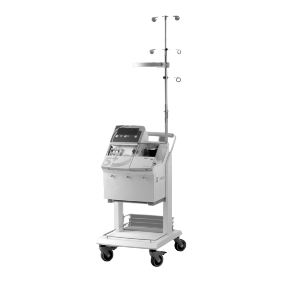
- Page 18 Presenting the Cell Saver 5+ System Figure 1-1, The Haemonetics Cell Saver 5+ P/N 53063-30, Manual revision: B...
-
Page 19: Introducing The Cell Saver 5+ System
Processing time has also been reduced while maintaining the highest quality end product. The Haemonetics Cell Saver 5+ system and its related accessory devices are intended to be used for the recovery of blood shed during or after an opera- tion, or as the result of trauma. -
Page 20: Contraindications For Use
Use of this bowl will allow blood to be available earlier for reinfu- sion to the patient. The Haemonetics Cell Saver 5+ system may also be used for pre-operative plasma sequestration. Contraindications for use... -
Page 21: Explaining Autologous Blood Transfusion
Presenting the Cell Saver 5+ System XPLAINING AUTOLOGOUS BLOOD TRANSFUSION Autologous blood is now widely accepted as the first choice for transfusion, whenever possible. The term autologous blood refers to blood which is derived from one individual. An autologous blood transfusion can be defined as a procedure in which a patient receives his or her own blood. -
Page 22: Historical Overview
Presenting the Cell Saver 5+ System Historical overview The following paragraphs summarize the history of transfusion methods. Early experiments with transfusion Some of the earliest recorded attempts at transfusion were undertaken by a French physician, Jean Denys, who in the 1660’s performed transfusions between animals and humans with predictably disastrous results Quite reasonably, the French government stepped in and forbade the trans- fusion of blood except with the permission of a member of the Faculty of... -
Page 23: Haemonetics Cell Saver Systems
RBCs, removing unwanted components, then pack the RBCs and return them to a transfer container for reinfusion. The first Haemonetics Cell Saver system was released in 1975. With each generation of the Cell Saver systems, Haemonetics has improved perfor- mance and increased automation. -
Page 24: Presenting Special Cell Saver 5+ Features
The CS5+ model improves upon the design and performance of its prede- cessors by processing shed blood faster without compromising the quality of the end product (packed RBCs). Haemonetics has improved and streamlined the features and functions of earlier units to meet the demands and needs of the modern operating room. -
Page 25: Final Blood Product Quality
Presenting the Cell Saver 5+ System <FG$ !"#$%&'(%&#)*&#+,--&.)/,0 1"#2&(34#)*(.*/0&#(03#6,7-#3/8',8(6-& 9"#:08)(--#)*,7- ;"#<(0=#)*(=8 >"#:08)(--#)*&#)?6/0=#*(%0&88 @"#A&)#?'#)*(-/0& B"#:08'&.)#(03#C/0/8* $%&88#ADE2D#),#%&8?5& Figure 1-2, Help display installation instructions Operators with multiple responsibilities involving frequent interruptions find the setup instructions useful as a checklist. If called away to attend to another duty, the operator can leave the setup instructions as a reminder, then return to the instruction list and continue from that point. -
Page 26: Listing The Cell Saver 5+ Specifications
Presenting the Cell Saver 5+ System ISTING THE AVER SPECIFICATIONS The CS5+ device is destined for continuous operation. Caution: The CS5+ equipment is not suitable for use in the presence of flam- mable anesthetic mixture with air or with nitrous oxide. The dimensions and weight of the CS5+ device are as follows: Characteristics Depth (cm) -
Page 27: Fluid Management Systems
Mobile RF communication equipment not approved by Haemonetics and portable communication equipment can affect the Cell Saver 5+ device. Any accessories and cables not approved by Haemonetics used in conjunc- tion with the device may increase hazards and influence compatibility with EMC requirements. -
Page 28: Maneuverability And Portability
Presenting the Cell Saver 5+ System Maneuverability and portability The CS5+ device is provided with a cart which has four caster wheels to ensure maneuverability. The unit may be tipped back on the rear wheels to roll over power cords, door sills, and other obstructions. The front two casters may be locked to secure the CS5+ cart in position. -
Page 29: Ordering Cell Saver
225 ml centrifuge bowl. Sterile fluid path, disposable, sin- gle use only. LN291E Cell Saver 5/5+ Bowl Set (70mL Bowl), single use only. LN02005-110EP Haemonetics Cell Saver 5+ system for 110 VAC. LN02005-220EP Haemonetics Cell Saver 5+ system for 220-240 VAC. 1-13 P/N 53063-30, Manual revision: B... -
Page 30: References
Presenting the Cell Saver 5+ System EFERENCES 1. “Guidelines for Blood Salvage and Reinfusion in Surgery and Trauma”, American Association of Blood Banks, 1997. 2. Geoffrey Keynes, ed., Blood Transfusion. Bristol: John Wright & Sons Ltd, 1949, pp. 15-16. 3. Geoffrey Keynes, ed., Blood Transfusion. Bristol: John Wright & Sons Ltd, 1949, p. -
Page 31: Components
Chapter Describing the Cell Saver 5+ System Components ....2-3 RESENTING THE AVER SYSTEM COMPONENTS Power switch and power entry module ..... 2-3 . - Page 32 Describing the Cell Saver 5+ System Components 1. Centrifuge cover 2. Centrifuge 3. Effluent line sensor 4. Power switch 5. Waste bag weigher 6. Valve and pump section 7. Keypad 8. Display screen Figure 2-1, The Cell Saver 5+ components P/N 53063-30, Manual revision: B...
-
Page 33: Resenting The Ell Aver System Components
Describing the Cell Saver 5+ System Components RESENTING THE AVER SYSTEM COMPONENTS This chapter identifies the major components of the Cell Saver 5+ system and explains their intended utilization. Detailed installation and operating instructions for the various protocols performed by the CS5+ device will be provided in subsequent chapters. -
Page 34: Display Screen
Describing the Cell Saver 5+ System Components ESCRIBING THE AVER CONTROL PANEL The control panel consists of a display screen and a keypad. Only the neces- sary readouts will be visible, thus helping the operator to focus on pertinent information. All control panel components are sealed and covered with a plastic membrane to protect the system from spills and allow for easy cleaning and disinfecting. -
Page 35: Keypad
Describing the Cell Saver 5+ System Components Keypad The CS5+ keypad is divided into two main sections: the Automatic control section of permanently visible keys. the Semi-automatic/Manual control section of backlit keys. Figure 2-4, The Cell Saver 5+ keypad The top four keys, Start, Stop, Mode and Help will be visible at all times during any type of CS5+ procedure. - Page 36 Describing the Cell Saver 5+ System Components Automatic control keys Figure 2-5, Automatic key section These four keys are “mode-insensitive” and will regulate the automatically controlled functioning of the CS5+ device in either the manual or automatic mode, as described in the following table. Purpose Start Used to initiate the first cycle of a set of cycles.
- Page 37 Describing the Cell Saver 5+ System Components Modify control keys Figure 2-6, Modify control key section These keys are also “mode-insensitive” and will allow the operator to change certain procedure parameters for a given CS5+ procedure and /or subsequent procedures. The keys become active during protocol selection, protocol setup and other various points during both automatic and manual operation.
- Page 38 Describing the Cell Saver 5+ System Components Process state keys Figure 2-7, Process state key section These keys can be used when backlit at specific points during the automatic mode; they will be permanently lit for use during the manual mode. Use will vary according to the selected CS5+ protocol as described in the following table: Purpose...
- Page 39 Describing the Cell Saver 5+ System Components Pump control keys Figure 2-8, Pump control key section These keys can be used to regulate the pump speed during any CS5+ proce- dure, however the increments of change will vary between the Cell Saving and Sequestering protocols, as described in the following table: Purpose Cell Saver: Used to increase the pump speed by incre-...
-
Page 40: Describing The Cell Saver 5+ Hardware Elements
Describing the Cell Saver 5+ System Components ESCRIBING THE AVER HARDWARE ELEMENTS The primary hardware elements of the CS5+ device consist of the centrifuge, a peristaltic blood pump, pinch valves and various sensors. Valves There are three pinch valves (also referred to as clamps) which occlude the three color-coded lines of the disposable set harness. -
Page 41: Air Detector
Describing the Cell Saver 5+ System Components Air detector This element uses ultrasound to detect air in the pump tubing leading to the centrifuge bowl. During the FILL or CONCENTRATE (CONC) process states, air bubbles are detected when the source of blood to be processed is exhausted. -
Page 42: Centrifuge Well
Describing the Cell Saver 5+ System Components Centrifuge well The centrifuge well contains a chuck to secure the bowl in place. There are no screws to tighten. The operator should place the bowl on the centrifuge chuck, close the centrifuge arm around the top of the bowl and lock the centrifuge knob. -
Page 43: Effluent Line Sensor
Describing the Cell Saver 5+ System Components Effluent line sensor The device is equipped with an effluent line sensor which monitors the quality of the bowl effluent (fluid to waste). The line sensor groove contains two optical sensors which are used to: Provide information regarding the wash status and advance the sys- tem to the EMPTY state once the proper effluent quality has been reached after a “minimum”... -
Page 44: Presenting The Disposable Set Elements
Describing the Cell Saver 5+ System Components RESENTING THE DISPOSABLE SET ELEMENTS A variety of disposable sets are available for use with the CS5+ device. This section provides a general understanding of the various elements, uses and operating characteristics. Detailed installation instructions and further speci- fications will be provided in subsequent chapters. -
Page 45: Receptacles And Collection Containers
Describing the Cell Saver 5+ System Components Receptacles and collection containers Every CS5+ disposable setup must be equipped with the following recepta- cles: a waste bag, a reinfusion bag and a source of unprocessed blood which may be either a collection reservoir or an extracorporeal circuit. A typical disposable set will have saline tubing and spikes to connect to a saline solu- tion source. -
Page 46: Centrifuge Bowl
Describing the Cell Saver 5+ System Components Centrifuge bowl The key component of the disposable set is the centrifuge bowl, where the RBCs are separated, washed, and packed. Both models of centrifuge bowls, the Latham bowl and the 70mL Bowl, consist of two subassemblies: an inner assembly which remains stationary and an outer assembly which rotates. -
Page 47: Describing The Operation Of The Bowl
Describing the Cell Saver 5+ System Components The two subassemblies of the bowl are joined with a rotary seal which forms a barrier between the inside and outside of the bowl. The effectiveness of the seal may be impaired if the bowl is incorrectly mounted in the chuck. Fully seating the bowl in the centrifuge chuck will ensure proper alignment. - Page 48 Describing the Cell Saver 5+ System Components The following series of drawings illustrate the operation of the bowl through the FILL-WASH-EMPTY states. Filling the bowl to the appropriate level as shown will give a hematocrit of at least 50% for the washed cells. The hematocrit may be increased by filling the bowl until the red cell interface is closer to the center of the bowl, however manually regulating the interface in this manner is not advised.
- Page 49 Describing the Cell Saver 5+ System Components 1. Blood is pumped From From in; separation Air to waste Supernatant collection collection begins as the bowl waste to reservoir reservoir spins. waste bag 2. The supernatant wastes overflow; RBCs stay in the Supernatant bowl.
- Page 51 Chapter Three Ensuring Safe Operation and Patient Care ..... 3-2 NDERSTANDING SAFE OPERATING PRACTICES Correctly storing and handling disposable material ... . 3-2 Avoiding electrical shock hazards .
-
Page 52: Understanding Safe Operating Practices
Ensuring Safe Operation and Patient Care NDERSTANDING SAFE OPERATING PRACTICES This chapter provides general information about: Safe operating practices for the CS5+ system. Precautions to take when providing patient care. Explanation about procedure parameters and processing times. The CS5+ device is intended to be used in locations which are free of flam- mable gases and vapors. -
Page 53: Working With Rotating Machinery
To comply with the IEC 60601-1-2:2001 Standard for Medical Electrical Equipment, general requirements for safety, it is not permitted to power the Cell Saver 5+ device using a power cord not supplied by Haemonetics, a multiple portable socket outlet or an extension cord. -
Page 54: Avoiding The Consequences Of Flow Restriction
If the bowl is empty, this could indicate a problem with the air detector and the operator should contact the local Haemonetics technical representative. P/N 53063-30, Manual revision: B... -
Page 55: Inspecting For Twists And Kinks In The Tubing
Ensuring Safe Operation and Patient Care Inspecting for twists and kinks in the tubing A careful inspection of the installed harness should be carried out to ensure that each section is correct installed on the CS5+ device and that all tubes are free of twists or kinks. -
Page 56: Avoiding Red Blood Cell Spillage
Ensuring Safe Operation and Patient Care Avoiding red blood cell spillage Under normal conditions there should be little or no red blood cell spillage and the effluent line sensor will reduce the occurrence of spillage. During the WASH state, two conditions may especially result in red blood cells spilling over into the waste bag: Overfilling of the bowl during manual processing. -
Page 57: Providing Safe Patient Care
Ensuring Safe Operation and Patient Care ROVIDING SAFE PATIENT CARE Reinfusing blood Gravity reinfusion of washed cells is accomplished more rapidly than infu- sion of the usual unit of homologous, packed cells because red blood cells suspended in saline are less viscous and are already at room temperature. The blue-coded harness line is primed at the factory with 20 ml of sterile air. -
Page 58: Factors Affecting Processing Time
Ensuring Safe Operation and Patient Care ACTORS AFFECTING PROCESSING TIME Cell Saving The time required to process a centrifuge bowl of salvaged blood depends on the following factors: Salvaged blood hematocrit. Bowl volume. Bowl filling rate. Wash volume. Wash flow rate. Empty flow rate. - Page 59 Chapter Four Preparing for a Cell Saver 5+ Procedure ....4-2 NDERSTANDING GENERAL SYSTEM OPERATION Collecting blood ........4-2 Filling the centrifuge bowl .
-
Page 60: Understanding General System Operation
Preparing for a Cell Saver 5+ Procedure NDERSTANDING GENERAL SYSTEM OPERATION This chapter provides a general overview of how the Cell Saver 5+ system works. Detailed instructions for each protocol performed by the CS5+ system are provided in Chapters Five, Six and Seven. Collecting blood The collection of blood is the simplest of the Cell Saver system tasks. -
Page 61: Washing The Red Blood Cells
Preparing for a Cell Saver 5+ Procedure Washing the red blood cells After the process described above has been completed, the optical sensors will detect that the RBC content of the bowl is sufficient to warrant washing (at least 50% hematocrit). The optical RBC sensor will initiate clamping the red-coded fill line and opening the yellow-coded wash line. -
Page 62: Initiating A Cell Saver 5+ Procedure
Preparing for a Cell Saver 5+ Procedure NITIATING A AVER PROCEDURE This section provides general details about initiating a procedure and installing a CS5+ system disposable set, regardless of how the system will be operated for a Cell Saver procedure. Variations will exist at certain points depending on whether the set contains a Latham bowl or a 70mL Bowl. -
Page 63: Explaining The Power On Procedure
Preparing for a Cell Saver 5+ Procedure Explaining the power on procedure When ready to initiate processing, the operator should: Press the power on switch located on the right side of the CS5+ " device. If the device has been powered off for less than six hours, the CS5+ system will provide the option of saving information as depicted in the following message: $IOF2#ICC#2F+IKF2S... - Page 64 Preparing for a Cell Saver 5+ Procedure The Self Test screen display will indicate the stage of self test completion and the current version of software installed in the device (CS5+-X.XX). If a fault is detected by the safety system, a Notice message with appropriate operator actions will be displayed as illustrated in the following example: AFGC#DFAD NID:+F...
-
Page 65: Explaining The Bowl Type Confirmation Message
Preparing for a Cell Saver 5+ Procedure Explaining the bowl type confirmation message Once the disposable set has been loaded on the CS5+ device, the system will automatically detect the size of the bowl and adjust the processing parameters accordingly. If for any reason the system cannot detect the type of bowl which has been installed, the following message will be displayed: QIOG#DS$F#+<I:+F... -
Page 66: Installing A Cell Saver Disposable Set
HELP installation list. Note: The setup instructions provided by the Help key are merely reminders and are not intended to serve as a substitute for formal Haemonetics training on the use of the CS5+ device. -
Page 67: Preparing The Device And Disposable Set
Preparing for a Cell Saver 5+ Procedure Hang the AC solution bag on the IV pole, then aseptically insert the " spiked end of the drip chamber into the AC solution bag. Ensure that the bag is properly labelled as anticoagulant solution. "... -
Page 68: Installing The Bowl
Preparing for a Cell Saver 5+ Procedure Installing the bowl For the 70mL Bowl First insert the chuck adapter into the centrifuge well. " The chuck adapter is NOT designed for single use and should be saved subsequent procedures. Symbol: DO NOT DISCARD Figure 4-7, Inserting the chuck adapter (for use with the 70mL Bowl) For all sets... -
Page 69: Installing The Tubing Harness
Preparing for a Cell Saver 5+ Procedure Figure 4-8, Securing the centrifuge bowl (steps A and B) Installing the tubing harness Place the valve tubing manifold in the tubing slots and thread the " pump tubing around the pump. Insert the tubing into the air detector. "... -
Page 70: Installing The Line Sensor Tubing
Preparing for a Cell Saver 5+ Procedure Close and lock the manifold latch and lock the pump lever. " Figure 4-10, Securing the tubing harness Close the fluid deck cover. " Installing the line sensor tubing For the Latham bowl sets Thread the effluent tubing through the effluent line sensor groove. -
Page 71: Hanging The Bags
Preparing for a Cell Saver 5+ Procedure For the 70mL Bowl set Locate the line sensor tubing section on the effluent tubing. " Thread the line sensor section through the effluent line sensor groove. " Ensure that the tubing is deeply inserted as depicted. "... -
Page 72: Connecting The Reservoir
Preparing for a Cell Saver 5+ Procedure Hang the waste bag on the pins on the front of the device as depicted. " Figure 4-14, Hanging the waste bag Verify that the waste bag is securely connected to the effluent line. "... -
Page 73: Setting Up The Saline Solution
Preparing for a Cell Saver 5+ Procedure Setting up the saline solution Hang the saline wash solution bags on the lower pigtail of the IV pole " so that they hang in a cascading manner. Close the clamps on both of the yellow-coded wash lines. "... -
Page 74: Entering The Standby State
Preparing for a Cell Saver 5+ Procedure Entering the STANDBY state Once the disposable set has been properly loaded, the operator can prepare the system for processing as follows: GIER#R:A$IAEQGF N(+- O*&0#3/8',8(6-&#/8#-,(3&3`#'%&88#ADE2D Figure 4-16, Load disposable screen message Press the Start key to enter the STANDBY state. "... -
Page 75: Performing A Procedure In The Automatic Mode
Chapter Five Cell Saving using Automatic Operation AUTOMATIC ... . . 5-2 ERFORMING A PROCEDURE IN THE MODE Explaining the STANDBY state......5-2 Filling the bowl . -
Page 76: Explaining The Standby State
Cell Saving using Automatic Operation AUTOMATIC ERFORMING A PROCEDURE IN THE MODE This chapter will explain how to operate the CS5+ device in the AUTOMAT- IC mode to perform cell salvage. The descriptions are applicable to all of the bowl types – the Latham bowls (225 ml and 125 ml) as well as the 70mL Bowl, unless specifically indicated otherwise in the text. -
Page 77: Filling The Bowl
Cell Saving using Automatic Operation This information indicates that the CS5+ system in the initial STANDBY state and processing will begin once the fluid in the collection reservoir reaches the preset level. At any time during the STANDBY state, the operator can ini- tiate the FILL state by either of the following actions: Pressing the Start key. - Page 78 Cell Saving using Automatic Operation Note: When the Latham bowl size is detected, it appears inside the bowl icon on the screen. Note: For the Latham bowl sets, the pump speed may vary as the bowl is being filled; for the 70mL Bowl set, the pump speed will remain constant. If the reservoir becomes empty before the bowl is full, the CS5+ system will revert to the STANDBY state and provide the following information: ADENRQS...
-
Page 79: Washing The Cells
Cell Saving using Automatic Operation Washing the cells When the CS5+ system detects that the bowl contains the appropriate quan- tity of red blood cells, the device will automatically enter the WASH state and provide the following information: OEA<#+FGGA EHDIJED:+ K,-?5&8#5- $2I+ 2F:NC... -
Page 80: Emptying The Bowl
Cell Saving using Automatic Operation Emptying the bowl When the appropriate volume of saline has entered the bowl, the CS5+ sys- tem will automatically stop the pump. The centrifuge will stop spinning and the red blood cells suspended in saline solution will be pumped from the bowl into the reinfusion bag. -
Page 81: Reinfusing Processed Blood
Cell Saving using Automatic Operation Reinfusing processed blood Reinfusion of the processed blood to the patient can begin as soon as there are red blood cells in the reinfusion bag. Collection of shed blood in the res- ervoir, filling the bowl, and reinfusing processed blood to the patient can oc- cur simultaneously throughout the procedure. -
Page 82: Explaining The Air Sensor Detection Messages
Cell Saving using Automatic Operation Explaining the air sensor detection messages Whenever the air sensor detects air in the disposable tubing during the EMP- TY state, the CS5+ system assumes that all RBCs have been transferred to the product bag from the bowl and the pump will stop. When air is detected during the FILL state, the system assumes that the reservoir is empty. - Page 83 Cell Saving using Automatic Operation To avoid a red cell spillage into the waste bag, the operator can: Press the Pause key and stop the pump. " The word “Pause” will flash on the screen display. Press the Pump slew keys to gradually adjust the pump speed. "...
-
Page 84: Describing Additional Auto Mode Functions
Cell Saving using Automatic Operation ESCRIBING ADDITIONAL AUTO MODE FUNCTIONS At any time during automatic operation, the operator can advance the sys- tem to manual operation by pressing the Mode key once. The operator can also use the Mode key to access an EMERGENCY mode, which may be used during a procedure to manage high blood loss situations. -
Page 85: Explaining The Concentrate State Option
Cell Saving using Automatic Operation If the operator presses the Modify key during the EMERGENCY mode to ac- cess the processing parameters, the following information will be displayed: +&--#A(T&%#AFDH$ FJF2[FN+S O(8*#T,-?5&P !MMM#5- $?5'#2Q+8#),P Q-?&#G/0& NI#OEA<#,')/,0P $%&88#E22IO#Z&48#),#.*(0=&#T(-?&8" $%&88#AFGF+D#),#(3T(0.&#*/=*-/=*)" $%&88#JIR:CS#7*&0#V/0/8*&3" Figure 5-7, Example of the EMERGENCY mode setup screen display The Wash Volume, Pump RBCs to (RETURN) and No WASH options are the only processing parameters which can be adjusted in the EMERGENCY mode. -
Page 86: Modifying Certain Processing Parameters
Cell Saving using Automatic Operation ADENRQS EHDIJED:+ K,-?5&8#5- $2I+ 1>1> 2F:NC O(8*#T,-?5&P 1MMM Q,7-8#'%,.&88&3P N&&3#;MM#5-#/0#%&8&%T,/%# ),#C:GG#(?),5()/.(--4 $%&88#ADE2D#),#V/--#6,7-#,%#+IN+#),#.,0.&0)%()&" $%&88#2FDH2N#),#&5')4#6,7-#/0),#%&8&%T,/%" $%&88#OEA<#),#7(8*#(#'(%)/(-#6,7-" Figure 5-8, Example of a STANDBY screen display Press the backlit Conc key to draw red blood cells from the reinfusion "... -
Page 87: Automatic Saving Of Modified Parameters
Cell Saving using Automatic Operation To modify the settings of the available processing parameters: Press the Modify key to access the automatic operation setup screen " display as follows: +&--#A(T&%#AFDH$ EHDIJED:+ J/0#7(8*#T,-?5&P !MMM#5- 2&8&%T,/%#-&T&-P LMM#5- 2&8?5&#()#-&T&-P ;MM#5- $?5'#2Q+8#),P Q-?&#G/0& NI#OEA<#,')/,0P G&T&-#8&08,%P E?),+4.-&P A'&&3#%&=?-()/,0P... -
Page 88: Pump Rbcs To (Return) Option
Cell Saving using Automatic Operation Press the Yes key to reset the modified parameter to the default set- " tings. Pump RBCs to (RETURN) option By default, the Pump RBCs to option is set at Blue Line, meaning that the packed red blood cells will automatically be sent through the blue-coded tubing to the reinfusion bag. -
Page 89: Minimum Wash Volume Option
Cell Saving using Automatic Operation When the system is in the RETURN state, the following information will be displayed. 2FDH2N EHDIJED:+ K,-?5&8#5- $2I+ 1>1> 2F:NC 11> O(8*#T,-?5&P 1MMM Q,7-8#'%,.&88&3P $?5'#%()&P# 9MM#5-U5/0 Figure 5-12, Example of the RETURN state screen display Once the bowl is empty, the CS5+ system will either initiate another FILL state if the level in the reservoir is above the preset level, or return to the STANDBY state. -
Page 90: No Wash Option
Cell Saving using Automatic Operation When performing a new prodedure, using the same type of bowl as the pre- vious procedure, the CS5+ system will check that the minimum wash vol- ume is not lower than the recommended one. If lower, the device will reset the minimum wash volume to the recommend- ed one, otherwise the CS5+ system will keep the previous minimum wash volume. -
Page 91: Reservoir Level And Resume At Level Options
To enable this feature, the operator should set the AutoCycle option to ON. Note: The ability to use this option must be enabled by Haemonetics field service. When this parameter is set at OFF, the FILL cycle can be started through level sensor detection or by pressing the Start key. -
Page 92: Speed Regulation Option
Cell Saving using Automatic Operation Speed regulation option As previously discussed, the pump speed in the FILL, CONC and WASH states is optimized according to the blood quality determined by the effluent line sensor. To disable this feature, the operator should set the Speed regula- tion option to OFF. -
Page 93: Viewing The Cell Saver System Status
Cell Saving using Automatic Operation IEWING THE AVER SYSTEM STATUS The following section provides information about the how procedure statis- tics are presented on the CS5+ display screen. C:GG#QIOG EHDIJED:+ K,-?5&8#5- $2I+ 1>1> 2F:NC 11> O(8*#T,-?5&P 1MMM Q,7-8#'%,.&88&3P $?5'#%()&P# @MM#5-U5/0 Figure 5-13, Example of a FILL state screen display The upper left section displays the current operating status of the device. -
Page 94: Wash Volume Monitoring
Cell Saving using Automatic Operation Wash volume monitoring During an automatic WASH state, an ongoing volume of wash solution used during the current wash cycle is displayed on the left side of the display screen, as visible in the following figure. OEA<#+FGGA EHDIJED:+ K,-?5&8#5-... - Page 95 Cell Saving using Automatic Operation Note: The CS5+ device can usually process 500 ml of fluid in approximately one minute. The product volume displayed to the operator will list approximately 20 ml more than what is contained in the reservoir because 20 ml of fluid remain trapped in the blue line until the end of the procedure.
-
Page 96: Summarizing Setting Variations
Cell Saving using Automatic Operation UMMARIZING SETTING VARIATIONS The following tables summarize the different values for default settings used throughout the various states of the Cell Saving protocol, depending on the type of centrifuge bowl in operation. Table 5-1, pump rate range State 70mL Bowl Latham 125... - Page 97 Chapter Cell Saving using Manual Operation MANUAL ....6-2 ERFORMING A PROCEDURE IN THE MODE Explaining the manual control keys ......6-3 Selecting manual operation .
-
Page 98: Performing A Procedure In The Manual Mode
Cell Saving using Manual Operation MANUAL ERFORMING A PROCEDURE IN THE MODE This chapter explains how to operate the CS5+ system in the MANUAL mode to perform cell salvage. The descriptions are applicable to all of the bowl types - the Latham bowls (225 ml and 125 ml) as well as the 70mL Bowl, unless specifically indicated otherwise in the text. -
Page 99: Explaining The Manual Control Keys
Cell Saving using Manual Operation Explaining the manual control keys The CS5+ device switches from automatic operation to manual operation when the Mode key is pressed. Once manual operation is selected, all backlit manual control keys will be continuously lit and become functional at different points in the procedure, depending on the current process state. -
Page 100: Selecting Manual Operation
Cell Saving using Manual Operation Selecting manual operation Prior to processing any blood, the disposable set must be installed as explained in Chapter Four. Once the CS5+ device has been powered on and the system self-test has been successfully completed, the initial STANDBY state message will appear. -
Page 101: Explaining The Recentrifugation Delay
Cell Saving using Manual Operation To modify the parameter settings: Press the Modify key to access the manual setup menu: " +&--#A(T&%#AFDH$ JENHEG C:GG#%()&P ;MM#5-U5/0 OEA<#%()&P LMM#5-U5/0 FJ$DS#%()&P ;MM#5-U5/0 +&0)%/V?='&&3P >@>M#%'5 O(8)(=#7&/=*&%P E-(%5#8,?03P $%&88#E22IO#Z&48#),#.*(0=&#T(-?&8" $%&88#AFGF+D#),#(3T(0.&#*/=*-/=*)" $%&88#JIR:CS#7*&0#V/0/8*&3" Figure 6-5, Example of the MANUAL mode setup menu Press the Select key to scroll the list and highlight the selected param- "... -
Page 102: Collecting Fluid In The Reservoir
Cell Saving using Manual Operation To avoid a red cell spillage into the waste bag, the operator can: Press the Pause key and stop the pump. " The word “PAUSE” will flash on the screen display. Press the Pump slew keys to gradually adjust the pump speed. "... -
Page 103: Using The Concentrate State
Cell Saving using Manual Operation The initial fill speed will be 400 ml/min until the bowl type is determined and the preset parameters will be in effect. The recommended maximum fill speeds are listed at the end of this chapter in Table 6-1, Pump rate range. Using the CONCENTRATE state To manually use the concentration option during the final fill cycle: Press the backlit Conc key. -
Page 104: Emptying The Bowl
Cell Saving using Manual Operation Emptying the bowl Once the red cells have been processed, the operator can send them to the reinfusion bag as follows: Press the Empty key. " When the system is advanced to the EMPTY state, the following information will be displayed: FJ$DS#QIOG JENHEG... -
Page 105: Reentering The Standby State
Cell Saving using Manual Operation A PRESSURE CUFF OR ANY OTHER MECHANICAL DEVICE MUST NOT BE USED WITH THE CS5+ DEVICE. PRESSURE REINFUSION CAN RESULT IN THE FATAL INFUSION OF AIR INTO THE PATIENT. Reentering the STANDBY state The CS5+ system will revert to the STANDBY state when it has detected that the bowl is empty. -
Page 106: Summarizing Parameter Variations
Cell Saving using Manual Operation UMMARIZING PARAMETER VARIATIONS The following table summarize the different values for default settings used throughout the various states of the cell saving protocol and which are recommended for use during manual operation. Table 6-1, Pump rate range State 70mL Bowl Latham 125... -
Page 107: Presenting The Cell Saver Sequestering Protocol
Chapter Seven Sequestering using the Cell Saver 5+ System ... . 7-2 RESENTING THE AVER SEQUESTERING PROTOCOL Describing method of sequestering ......7-2 . -
Page 108: Describing Method Of Sequestering
Typically the pH is 7.02 at 6 hours and 7.01 at 24 hours post-collection when stored in accordance with the current applicable standards. Data on file at Haemonetics Corporation. Actual results may vary depending on patient platelet pre-count, hematocrit, height, weight, physical condition, etc. -
Page 109: Initiating A Sequestering Procedure
Sequestering using the Cell Saver 5+ System NITIATING A SEQUESTERING PROCEDURE Prior to processing any blood, the disposable set must be correctly installed on the CS5+ device according to installation instructions for the standard processing set described in Chapter Four and the Directions for Use (DFU) provided with the sequestering set. - Page 110 Sequestering using the Cell Saver 5+ System The following information will be displayed and the operator should proceed as follows: +&--#A(T&%#AFDH$ EHDIJED:+ J/0#O(8*#T,-?5&P !MMM#5- 2&8&%T,/%#-&T&-P LMM#5- 2&8?5&#()#-&T&-P ;MM#5- $?5'#2Q+8#),P Q-?&#G/0& NI#OEA<#,')/,0P G&T&-#8&08,%P E?),+4.-&P A'&&3#%&=?-()/,0P $%,),.,-P +&--#A(T&% $%&88#E22IO#Z&48#),#.*(0=&#T(-?&8" $%&88#AFGF+D#),#(3T(0.&#*/=*-/=*)" $%&88#JIR:CS#7*&0#V/0/8*&3" Figure 7-2, Example of the Cell Saver setup menu Press the Select key until Protocol is highlighted.
-
Page 111: Setting The Processing Parameters
Sequestering using the Cell Saver 5+ System Setting the processing parameters Performing sequestering is a MANUAL operation requiring operator inter- vention to move from one stage to another. The process should be completely understood before the sequestering protocol is used. The preset parameters for both sequestering methods are set at: Pump draw rate: 60 ml/min. -
Page 112: Processing From Blood Bags
Sequestering using the Cell Saver 5+ System ROCESSING FROM BLOOD BAGS Using this method to sequester plasma, the operator will first need to collect whole blood from the patient via a short intravenous or arterial cannula into blood bag(s) containing anticoagulant solution. Warning: Only one (1) unit of blood should be collected and processed at a time. -
Page 113: Emptying The Bowl
Sequestering using the Cell Saver 5+ System Caution: Both clamps should never be closed at the same time. Continue to observe the centrifuge bowl as it fills. " Plasma should flow into the PPP bag at a consistent flow rate until the white buffy coat band (made up of platelets and white cells) which is immediately adjacent to the top of the red cell layer reaches the shoulder of the bowl. -
Page 114: Transferring The Rbcs For Reinfusion
Sequestering using the Cell Saver 5+ System When the bowl is completely empty, the pump will stop and the following information will be displayed: ADENRQS A&a?&8)&% K,-?5&8#5- $2I+ 2F:NC Q,7-8#'%,.&88&3P $%&88#ADE2D#),#V/--#6,7-" $%&88#JIR:CS#),#.*(0=&#'(%(5&)&%8" $%&88#SFA#),#8&-&.)#+&--#A(T&%#'%,),.,-" Figure 7-7, Example of the STANDBY state screen display Transferring the RBCs for reinfusion The red blood cells can now be drained to a transfer bag for reinfusion to the patient if needed. - Page 115 Sequestering using the Cell Saver 5+ System Warning: Care must be exercised when sequestering plasma. A 225 ml bowl can yield 800 ml or more of plasma and cause hypovolemia if fluid balance is not carefully maintained. Many variables influence the amount of plasma which can be sequestered and the volume to be sequestered must be determined by an attending physician.
-
Page 116: Completing The Sequestering Procedure
Sequestering using the Cell Saver 5+ System OMPLETING THE SEQUESTERING PROCEDURE Removing the plasma product After the final sequestering pass, the operator should disconnect the plasma product as follows: Remove the collection bags from the pins and invert the bags. "... -
Page 117: Selecting The Cell Saving Protocol
Sequestering using the Cell Saver 5+ System Selecting the cell saving protocol The STANDBY state screen display will be visible at this time. ADENRQS A&a?&8)&% K,-?5&8#5- $2I+ 2F:NC Q,7-8#'%,.&88&3P $%&88#ADE2D#),#V/--#6,7-" $%&88#JIR:CS#),#.*(0=&#'(%(5&)&%8" $%&88#SFA#),#8&-&.)#+&--#A(T&%#'%,),.,-" Figure 7-8, Example of the STANDBY screen display (sequester) To perform a cell salvage procedure once the plasma sequestering proce- dure is complete, the operator should: Press the Yes key to select the Cell Saver protocol. - Page 119 Chapter Eight Using Data Acquisition Features ..... . . 8-2 ROVIDING AN OVERVIEW OF THE FEATURES Listing the recorded parameters ......8-2 Explaining the output devices .
-
Page 120: Providing An Overview Of The Features
Copying information displayed by the CS5+ device during operation. Introducing this information on a computer terminal. To implement this, Haemonetics has introduced on the CS5+ device a choice of data acquisition tools including: The automatic recording of the parameters describing the autotransfu- sion process. -
Page 121: Explaining The Output Devices
Using Data Acquisition Features Patient ID: a 10 digit number identifying the patient (social security number, hospital file number, etc.). Volume accounting functions: the total processed volume, the total reinfused volume, the total washed volume and the number of bowls processed. -
Page 122: Explaining On - Line Data Acquisition Features
Using Data Acquisition Features XPLAINING ON LINE DATA ACQUISITION FEATURES On-line data acquisition features are tools which the operator can access during the current CS5+ procedure. The following features are available during the course of each procedure: Viewing the current procedure statistics. Transferring the current recorded values to an output device. -
Page 123: Transferring Procedure Data
Using Data Acquisition Features The current values of the recorded parameters will be displayed. Note: The following information will also be displayed if the option was set in the utilities menu: *EBL Patient (35%), **EPL Patient. At this point the operator can choose among the following actions: Press the Stop key to return to STANDBY mode. -
Page 124: Optionally Entering Certain Data
Using Data Acquisition Features Optionally entering certain data By default, the patient ID and the surgery type should be entered in the upper right section of the View Data screen display. However, if the techni- cian has set the option in the utilities menu, the patient ID number and surgery type may also be entered in a dedicated screen display. -
Page 125: Explaining Off Line Data Acquisition Features
Using Data Acquisition Features XPLAINING OFF LINE DATA ACQUISITION FEATURES Off-line data acquisition features are tools designed for the management of information recorded during a previous autotransfusion procedure and are not accessible during the cell saving process for safety reasons. During each procedure parameters are automatically stored in the CS5+ memory. - Page 126 Using Data Acquisition Features If the CS5+ device has been powered off for less than 6 hours, the following information will appear: $IOF2#ICC#2F+IKF2S $,7&%#*(8#6&&0#,VV#V,%#!1#5/0?)&W8X +,0)/0?&#)*&#'%&T/,?8#'%,.&3?%&#Y $%&88#SFA#),#Z&&'#'%&T/,?8#3()(" $%&88#NI#),#6&=/0#(#0&7#'%,.&3?%&" $%&88#JIRF#),#&0)&%#8)()/8)/.8#5&0?" Figure 8-6, Example of the Power off recovery message In either case, the operator can access the off-line data acquisition menu and select an off-line data acquisition function as follows: Press the Mode key to receive the following screen display: "...
-
Page 127: Working With The Transfer Data Function
Using Data Acquisition Features Working with the Transfer Data function The Transfer Data screen display will allows the operator to transfer the recorded information for a selected procedure to an output device connected to the CS5+ device. When it is selected from the off-line data acquisition menu, the following information will be displayed: D%(08V&%#3()( $%,.&3?%&#b... -
Page 128: Working With The View Data Function
Using Data Acquisition Features The operator should remember that the CS5+ device does not control the data transfer and therefore should verify the following points: The output device has been properly connected. The output device has actually received the information sent. The entire data transfer is correct. -
Page 129: Working With The Set Time Function
Using Data Acquisition Features When the View Data information is displayed, the following keys will be available to the operator: Arrow keys: allows the operator to display all of the procedures avail- able. When selected, the View Data screen display will list the first procedure stored in memory (Procedure #1). -
Page 130: Working With The Clear Data Function
Using Data Acquisition Features The information will be presented as follows: Current time: listed by hour and minutes. Current date: listed by day of the week, date, month and year. To modify the time and date: Press the Select key to scroll the list and highlight an item. "... -
Page 131: Listing Data Output Devices
Using Data Acquisition Features ISTING DATA OUTPUT DEVICES The following options are available for use with the CS5+ system: Printer1 Transmission at 9600 bauds, data alignment using TAB (09h) con- trol character, suitable for printers with 80 or more characters per line. - Page 133 Chapter Nine Maintaining the Cell Saver 5+ Device ....9-2 ROVIDING AN OVERVIEW OF NORMAL MAINTENANCE ..... . 9-3 ESCRIBING SPECIFIC CLEANING PROCEDURES Cleaning the optical lenses .
-
Page 134: Providing An Overview Of Normal Maintenance
A record should be kept regularly of the date and type of maintenance performed. Haemonetics recommends a maintenance visit once or twice a year by an authorized Haemonetics technician who will perform a series of mainte- nance controls and fine-tune the device for maximum performance. The local Haemonetics representative can be contacted for details of a Preven- tive Maintenance Plan (PMP) for the CS5+ equipment. -
Page 135: Describing Specific Cleaning Procedures
The clips must be thoroughly cleaned after any spills. A dirty or blocked clip may no longer hold the bowl correctly in place. If a clip is not functioning properly, the operator must contact an authorized Haemonetics representative. Cleaning the fluid detectors... -
Page 136: Cleaning After A Spill
Maintaining the Cell Saver 5+ Device Cleaning after a spill The exterior surfaces of the CS5+ device including the control panel, should be cleaned with a mild detergent or disinfectant solution at regular intervals, as well as following any spill. Caution: The operator should never use full-strength bleach directly on the device;... -
Page 137: Providing Customer Service
These technical specialists are available to diagnose and repair any malfunctions with the blood processing equipment and will be on site as soon as possible. The authorized Haemonetics technician can answer any questions about routine maintenance and quality control as well as provide routine annual or semi-annual maintenance, such as leakage current tests. - Page 138 Maintaining the Cell Saver 5+ Device In some cases, it may be necessary to dispose of the contaminated goods after reporting the problem to the Haemonetics representative. This should be done according to the locally established guidelines pertaining to the disposal of biologically contaminated material.
- Page 139 Appendix Providing Reference Information OMPLICATIONS OF AND CONTRAINDICATIONS TO PERIOPERATIVE ......... A-2 BLOOD RECOVERY .
-
Page 140: Complications Of And Contraindications To Perioperative Blood Recovery
Providing Reference Information OMPLICATIONS OF AND CONTRAINDICATIONS TO PERIOPERATIVE BLOOD RECOVERY Table A-1, Complications of and contraindications to perioperative blood recovery* Substance Effects Recommended Action Pharmacologic Agents A. Clotting Agents 1. Microfibrillar Products May cause platelet aggrega- Avoid aspiration when prod- Examples: tion and clot formation. - Page 141 Providing Reference Information Table A-1, Complications of and contraindications to perioperative blood recovery* Substance Effects Recommended Action 3. Betadine Causes red cell lysis. Avoid aspiration in area where product is being used. Resumption is an option after copious irrigation with 0.9% sodium chloride solution to an alternate suction source.
- Page 142 Providing Reference Information Table A-1, Complications of and contraindications to perioperative blood recovery* Substance Effects Recommended Action C. Methylmethacrylate 1. Liquid or powder form May cause circulatory col- Avoid aspiration in area lapse. where product is being used. Resumption is an option after copious irrigation with 0.9% sodium chloride solution to an alternate suction source.
- Page 143 Providing Reference Information Table A-1, Complications of and contraindications to perioperative blood recovery* Substance Effects Recommended Action Proteolytic enzyme may Do not aspirate into system. E. Gastric and Pancreatic cause red cell lysis. Resumption is an option after Fluid copious irrigation with 0.9% sodium chloride solution to an alternate suction source.
- Page 144 Providing Reference Information Table A-1, Complications of and contraindications to perioperative blood recovery* Substance Effects Recommended Action Potential for marked hyperten- Avoid aspirating at the tumor C. Pheochromocytoma sion due to high concentra- site. tions of catecholamines. Resumption is an option after copious irrigation with 0.9% sodium chloride solution to an alternate suction source.
-
Page 145: Describing Cell Saver
Providing Reference Information ESCRIBING AVER ERROR CODES The CS5+ data acquisition will automaticaly store all critical errors occur- ring during a procedure using codes. The following table lists these error codes with a brief description: Code Error message on the screen Description System error. - Page 146 Providing Reference Information Code Error message on the screen Description System error. Software definition error. Software definition error. System error. Software read error. Software read error. System error. Software queue error. Software queue error. System error. Software write error. Software write error. Centrifuge error.
- Page 147 Sensor output is out of specification. and disposable. Unexpected sensor reading. Analog-to-digital converter error. Precisionsensor input test. Restart machine. If failure continues, call Haemonetics hot- line. System error. Air detector error. Air detector. Waste bag full. Waste bag full error.
- Page 148 Providing Reference Information Code Error message on the screen Description Pump error. Pump stalled error. Clean pump rotor. Pump rotation is blocked. Check tubing positioning. Pump error. Incorrect pump speed. Incorrect pump speed detected. Pump speed target could not be reached. Please be sure pump platen and valve Pump lever or manifold latch error.
-
Page 149: Presenting The Cs5+ Compatible Printer
Providing Reference Information CS5+ RESENTING THE COMPATIBLE PRINTER The Cell Saver 5+ can be connected to a non-thermal printer, presented below. Note: To ensure long life of the printer and compliance with warrantly requirements, it is recommended to use the paper and ribbon reference on page A-12 of this manual. -
Page 150: Ribbon Installation
Providing Reference Information Push the Feed button to continue printing. " Close the lid, ensuring the paper pass through the guideline lid. " Ribbon installation If the printout is no longer readable, the operator should verify the ribbon state. If the ribbon is not finished, the operator shoud proceed as follows: Open the printer lid. -
Page 151: Electromagnetic Immunity
Providing Reference Information IEC 60601-1-2:2001 XPLAINING STANDARD REQUIREMENTS Electromagnetic immunity The Cell Saver 5+ system is intended for use in the electromagnetic environ- ment specified in the following tables and the operator must ensure that each system is used in such an environment. IEC 60601-1-2:2001, Table 201: Guidance and manufacturer’s declaration - electromagnetic immunity Emissions test... - Page 152 Providing Reference Information IEC 60601-1-2:2001, Table 202: Guidance and manufacturer’s declaration - electromagnetic immunity Immunity test IEC 60601 test Compliance Electromagnetic environment level level guidance Electrostatic dis- ± 6 kV contact ± 6 kV contact Floors should be wood, concrete charge (ESD) or ceramic tile.
- Page 153 Providing Reference Information IEC 60601-1-2:2001, Table 204: Guidance and manufacturer’s declaration - electromagnetic immunity Immunity test IEC 60601 Compliance Electromagnetic environment guidance test level level Portable and mobile RF communication equipment should be used no closer to any part of the CS5+ system, including cables, than the recommended separation distance calculated from the equation applicable to the frequency of the transmitter.
- Page 154 Providing Reference Information The CS5+ system is intended for use in an electromagnetic environment in which radiated RF disturbances are controlled. The customer or the user of the CS5+ system can help prevent electromagnetic interference by maintain- ing a minimum distance between portable and mobile RF communications equipment (transmitters) and the CS5+ system as recommended below, according to the maximum output power of the communications equipment.
Need help?
Do you have a question about the Cell Saver 5+ and is the answer not in the manual?
Questions and answers