Table of Contents
Advertisement
Quick Links
Advertisement
Table of Contents

Subscribe to Our Youtube Channel
Summary of Contents for Dynon SV-INTERCOM-2S
- Page 1 Installation and User Guide This product is not approved for installation in type certificated aircraft. 102061-000 Revision B 8/23/2021 Copyright © 2021 by Dynon Avionics, Inc. Dynon Avionics grants third parties' permission to print this document...
- Page 2 Information in this document is subject to change without notice. Dynon Avionics reserves the right to change or improve its products and to make changes in the content without obligation to notify any person or organization of such changes.
- Page 3 ABOVE LIMITATIONS MAY NOT APPLY TO YOU. Dynon Avionics retains the exclusive right to repair or replace the instrument or firmware or offer a full refund of the purchase price at its sole discretion. SUCH REMEDY SHALL BE YOUR SOLE AND EXCLUSIVE REMEDY FOR ANY BREACH OF WARRANTY.
- Page 4 ECO # 126683 Initial Release • Reformatted document using new template. • Added information for SV-COM-T25 and SV-COM-T8 July, 2021 ECO # 348817 radios. • Revised Dual Radio PTT Installation section. SV-INTERCOM-2S - Installation and User Guide, Revision B Page | i...
-
Page 5: Table Of Contents
Table of Contents Introduction ....................3 Dynon Avionics Product Registration ................3 Warranty Information ....................3 Printing This Document ....................3 Document Iconography ....................4 Related Documents ...................... 4 System Overview..................5 Installing the SV-INTERCOM-S2 .............. 6 Mechanical Installation ....................6 Electrical Installation ..................... -
Page 6: Introduction
/ user-serviceable parts. Units found to have been taken apart may not be eligible for repair under warranty. Additionally, once a Dynon Avionics unit is opened, it is not considered airworthy and must be serviced at the factory. -
Page 7: Document Iconography
The following icons are used in this guide: This icon denotes information that merits special attention. This icon denotes a helpful tip. Related Documents • SkyView System Installation Guide Page | 4 SV-INTERCOM-2S - Installation and User Guide, Revision B... -
Page 8: System Overview
• Dual Radio Capability — dual radio outputs allow two third-party radios, or a third-party radio and a Dynon SV-COM-T25/T8 radio, to operate alongside one another. • Fail-Safe — immediate pilot headset switch-over to primary radio, allowing communication without intercom power. -
Page 9: Installing The Sv-Intercom-S2
Do not use Figure 3 as a template to cut instrument panel. Do not rivet the SV-INTERCOM-2S directly to the aircraft as this will hinder future removal if necessary. The SV-INTERCOM-2S kit includes #6-32 hex-drive round head fasteners. Fasteners are 5/8" in length and require a 5/64" hex drive tool. - Page 10 Figure 4: Space Requirements (Not to Scale) SV-INTERCOM-2S - Installation and User Guide, Revision B Page | 7...
-
Page 11: Electrical Installation
Electrical Installation The SV-INTERCOM-2S has one D25M connector for connection to SkyView and other devices. Installers will need to fabricate a D25F wire harness. 20 AWG wire is recommended for power and ground wires; 22 AWG wire is recommended for all other connections. Shielded wire is required for audio connections (see Section 3.2.1... - Page 12 Music In, Left connected to the stereo Music In jack on the front of the Intercom. SV-COM-T25/T8 #1: D15, Pin 23 Radio 1 Microphone SV-COM-425 #1: Output D15, Pin 1 SV-INTERCOM-2S - Installation and User Guide, Revision B Page | 9...
- Page 13 Connecting these grounds to the shield (which is also grounded at pin 1) at the intercom end of the harness is a suitable way to accomplish this goal. Page | 10 SV-INTERCOM-2S - Installation and User Guide, Revision B...
- Page 14 Connecting these grounds to the shield (which is also grounded at pin 1) at the intercom end of the harness is a suitable way to accomplish this goal. SV-INTERCOM-2S - Installation and User Guide, Revision B Page | 11...
- Page 15 Connecting these grounds to the shield (which is also grounded at pin 1) at the intercom end of the harness is a suitable way to accomplish this goal. Page | 12 SV-INTERCOM-2S - Installation and User Guide, Revision B...
- Page 16 SV-INTERCOM-2S's MASTER GROUND (Pin 1). Additionally, the point should be as close to the SV-INTERCOM-2S side of your harness as possible. SV-INTERCOM-2S - Installation and User Guide, Revision B...
- Page 17 If using nylon washers, discard the steel washer included with the kit. Figure 8: Audio Jack Installation Page | 14 SV-INTERCOM-2S - Installation and User Guide, Revision B...
- Page 18 3.2.2 Dual Radio PTT Installation The SV-INTERCOM-2S has two separate radio outputs that can be connected to individual COM radios. In a dual COM radio installation, the PPT output signal (Radio PTT (Pin 12)) requires an external switch to control which radio receives the PTT output signal, and thus transmits.
- Page 19 Figure 10: Dual COM Radio PTT Electrical Connections Page | 16 SV-INTERCOM-2S - Installation and User Guide, Revision B...
-
Page 20: Using The Sv-Intercom-2S
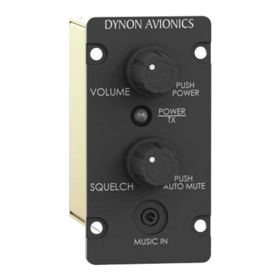
LED Power/Transmit Indicator The LED indicator light in the center of the SV-INTERCOM-2S faceplate is green when the the unit is powered on. When either the pilot or co-pilot PTT switch is depressed, the LED becomes orange to indicate radio transmission. -
Page 21: Front Music In Jack
Fail-safe Operation When power is lost or the SV-INTERCOM-2S is powered off, the primary radio is connected directly to the pilot’s headset. If the pilot headset is a stereo headset, radio audio will only be heard in one ear. Intercom conversation and audio from other radios and inputs (including music) will not be heard when in this unpowered fail-safe mode.
Need help?
Do you have a question about the SV-INTERCOM-2S and is the answer not in the manual?
Questions and answers