Table of Contents
Advertisement
Advertisement
Table of Contents

Related Manuals for Gymna ShockMaster 500


Summary of Contents for Gymna ShockMaster 500
- Page 1 USER MANUAL é ShockMaster 500 & ShockMaster 300 0344...
- Page 2 ELOE006-GA501-V4.3.0 Page 2 of 85...
- Page 3 Unauthorised reproduction, either in whole or part, of the software provided with this product is strictly prohibited and is subject to prosecution. All rights reserved. Manufacturer: GymnaUniphy N.V. Pasweg 6A 3740 Bilzen Belgium T +32 (0) 89 510.532 info@gymna.com www.gymna.com ELOE006-GA501-V4.3.0 Page 3 of 85...
-
Page 4: Table Of Contents
1.3 Prerequisites for operating the ShockMaster ............10 Operator ...................... 10 Training of the operator ................. 11 1.4 Description of controls and functional elements ShockMaster 500 ......12 1.5 Description of controls and functional elements ShockMaster 300 ......14 General safety information ................. 16 Installation...................... - Page 5 5.5.2.8 Soft Start ....................59 5.5.2.9 Dynamic protocol (pGTS) ................59 Software update ................... 60 Cleaning, Maintenance, Disposal, Repair ............61 6.1 Cleaning ......................61 Cleaning the ShockMaster main unit and ShockMaster 500 trolley ....... 61 ELOE006-GA501-V4.3.0 Page 5 of 85...
- Page 6 8.4 Coupling Gel ...................... 73 8.5 Documentation ....................74 Technical specifications ..................75 9.1 Technical data of ShockMaster 500 ............... 75 9.2 Technical data of ShockMaster 300 ............... 76 9.3 Conformity with directives ................... 77 9.4 Conformity with standards ................... 77 9.5 EMC guidance and manufacturer’s declaration ............
-
Page 7: General Information
General Information Introduction This manual contains warnings, safety instructions and specific operating instructions in accordance with liability regulations. CAUTION Complete or partial failure to observe the instructions, information or procedures preceded by the term “CAUTION” may cause injury or fatal accidents. ATTENTION Complete or partial failure to observe the instructions, information or procedures preceded by the term “ATTENTION”... -
Page 8: Device Description
CAUTION Before you start using the ShockMaster for the first time, please make sure you have read and understood all information provided in this user manual and accessory manual(s) of detachable component(s). Familiarity with the information and instructions contained in this manual is an essential requirement to ensure efficient and optimal use of the device, to avoid dangers to persons and to the equipment and to obtain good treatment results. -
Page 9: Intended Use
Intended use The ShockMaster is designed for extracorporeal treatment by means of low- to medium-energy radial shockwaves in the following fields of application: Biomechanical therapy Myofascial trigger points (MTrP) Disorder of tendon insertions Activation of muscle and connective tissue ... -
Page 10: Side Effects
open scar vertebrae, spinal column or head Side effects Treatment with the ShockMaster may cause the following side effects: swelling, reddening, haematomas petechiae, pain, irritation of the periosteum skin lesions after previous cortisone therapy cardiac arrhythmias These side effects generally disappear after 5 to 10 days. -
Page 11: Training Of The Operator
However, you can also contact the following address directly: GymnaUniphy nv Pasweg 6A 3740 Bilzen Belgium Tel.: +32 (0) 89 510 532 info@gymna.com ELOE006-GA501-V4.3.0 Page 11 of 85... -
Page 12: Description Of Controls And Functional Elements Shockmaster 500
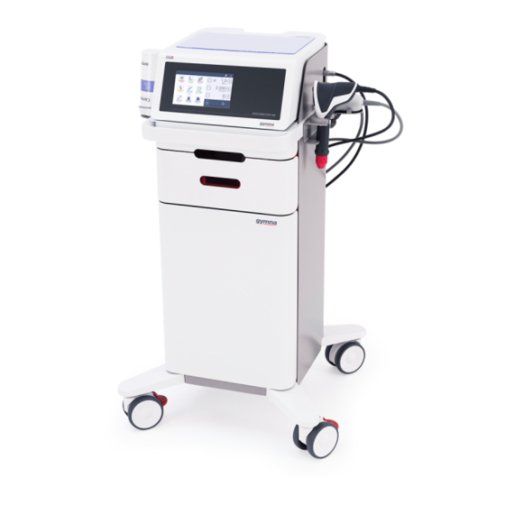
Description controls functional elements ShockMaster 500 LCD TFT touch screen RSW handpiece 1. Connector RSW/V-actor handpiece channel black 2. Connector RSW/V-actor handpiece channel yellow ELOE006-GA501-V4.3.0 Page 12 of 85... - Page 13 1. USB connector (type A) 2. Compressed air inlet 3. Auxiliary power outlet for the compressor 4. Mains supply inlet 5. Mains fuses holder 6. Mains switch 7. Sign “Consult and observe the instructions for use” NOTE The USB connection is only suitable for connecting a USB memory stick that supports the USB V1.1 protocol.
-
Page 14: Description Of Controls And Functional Elements Shockmaster 300
Description controls functional elements ShockMaster 300 1. LCD TFT Touch Screen 2. Connector RSW/V-actor handpiece 3. V-actor ii ELOE006-GA501-V4.3.0 Page 14 of 85... - Page 15 1. USB connector (Type A) 2. Pressure filter housing 3. Read the manual first 4. Mains power inlet 5. Mains fuse holder 6. Mains switch NOTE The USB connection is only suitable for connecting a USB memory stick that supports the USB V1.1 protocol.
-
Page 16: General Safety Information
General safety information CAUTION The ShockMaster is exclusively intended for use by medical specialists and must only be used by suitably qualified and trained medical personnel (see also section 1.3 Prerequisites for operating the ShockMaster ) The user is responsible for correctly positioning the handpiece of the ShockMaster and determining where the treatment zone of the patient is located. - Page 17 Never cover the device when in use! Especially the ventilation slots of the trolley (ShockMaster 500) need to be kept free. Make absolutely sure that no liquid can seep into the device housing or handpiece. Any damage to the unit resulting from incorrect operation is not covered by the manufacturer’s warranty.
- Page 18 NOTE ShockMaster meets requirements applicable electromagnetic compatibility (EMC) standard IEC / EN 60601-1-2. These limits are designed to provide reasonable protection against harmful interference in a typical medical installation. The equipment generates, uses and can radiate radio frequency energy. If not installed and used in accordance with these instructions, the equipment may cause harmful interference to other devices in the vicinity.
- Page 19 ATTENTION Before the ShockMaster can be cleaned and disinfected, the device must be switched off and must be separated from the supply mains (see above). The ShockMaster and accessories must be initially cleaned and disinfected prior to entry into service as well as before each use. While performing cleaning / disinfection work, ensure that the work environment is properly ventilated.
-
Page 20: Installation
Tissue Box Protective anti-skid mat User manual of the ShockMaster 500 (hard copy in English, other languages available on CD) User manual of the compressor (hard copy in English) User manual of the RSW handpiece short (hard copy in English, other languages available on ... -
Page 21: Shockmaster 300
ShockMaster 300 The standard scope of delivery of the ShockMaster 300 includes the following items ShockMaster 300 (radial shockwave device included integrated air compressor) Complete RSW handpiece short (1 metal projectile + tube included) Extra metal projectile and metal tube ... -
Page 22: Device Installation
Device Installation CAUTION Carefully follow the instruction guideline for the device installation step by step. Compressor Installation ShockMaster 500 Preparation Fig. 1 Remove red cap (transport protection) Fig. 2 Assemble air filter ELOE006-GA501-V4.3.0 Page 22 of 85... - Page 23 Fig. 3 Connect air hose if it is separately supplied Fig. 4 Turn the tap in the open position (in line with the air flow). Fig. 5 Turn the start switch to position “1” ELOE006-GA501-V4.3.0 Page 23 of 85...
- Page 24 Trolley bay for the compressor Fig. 6 Open the front door of the trolley Fig. 7 Place the compressor into the trolley (as in the picture) Fig. 8 Insert the compressor mains plug into the socket of the trolley ELOE006-GA501-V4.3.0 Page 24 of 85...
- Page 25 Fig. 9 Place the air hose and power cord on top of the trolley, as in the picture, and insert the cable into the clamp. Close the front door of the trolley. After connecting the compressor and the control unit, switch on the device and check both manometers of the compressor: Fig 10 Check Manometer on left hand side: should have a...
-
Page 26: Connections At The Rear Of The Control Unit
Before connecting the device with the power mains, verify if the ratings on the type label of the compressor match with the supply mains properties. The ShockMaster 500 must be connected to a properly installed outlet with the original power cord provided by the manufacturer. -
Page 27: Shockmaster 300
3.4.2.2 ShockMaster 300 Connect the supplied power cord to the mains power inlet on the rear of the device. Plug the power cord into the wall socket. ATTENTION When setting up the instrument, make sure that the ventilation holes in the housing of the ShockMaster 300 is not blocked. - Page 28 ATTENTION Consider the colour marks for ShockMaster 500. Connect the handpiece with the black mark on the cable only with the black output channel. The yellow channel can be used for an extra handpiece or a V-actor ® Ensure the red spot on the connector match the red spots on the handpiece or V-actor connector.
- Page 29 ShockMaster 300 ShockMaster 500 1. Holder handpiece short 2. Holder handpiece 3. Optional holder V-actor ELOE006-GA501-V4.3.0 Page 29 of 85...
-
Page 30: Operation
Operation Functional check Perform the following functional checks after the system has been installed: Check the control unit and handpieces for damage. Switch on the ShockMaster Set the energy level to 1.5 bar and frequency 5 Hz. ... -
Page 31: Treatment
Always read chapter 2 General safety information before starting a treatment. Please refer to the separate operating instructions for the handpiece. Each time after the ShockMaster 500 has been transported, make sure that all functional checks have been performed on the unit before you start treatment. - Page 32 CAUTION Treatment should be interrupted latest after 6.000 pulses! The contact surface of the applicator could overheat! ELOE006-GA501-V4.3.0 Page 32 of 85...
-
Page 33: The User Interface
The user interface NOTE All following representations of menus are examples and no treatment proposals Introduction The ShockMaster software contains a treatment menu (=main menu), an application menu (containing submenus) and system buttons: Treatment menu Pressure Number of shocks Frequency Actual number of shocks ... -
Page 34: Home Screen
Home Screen Home screen ShockMaster 500: System buttons Application Treatment menu menu Home screen ShockMaster 300: System buttons Treatment Application menu menu ELOE006-GA501-V4.3.0 Page 34 of 85... -
Page 35: Treatment Menu
Treatment menu Enable/disable Current value of Increase Decrease parameter. corresponding corresponding pressure soft- parameter. parameter. start option Reset the actual Actual number number of shocks. shocks with progression bar. The “treatment menu” is the main menu that displays after the device is powered on. In this menu the three parameters (pressure, amount of shocks and shock frequency) can be adjusted by the user. -
Page 36: Parameters
Parameters 5.3.1.1 Pressure The pressure parameter in ShockMaster500 can be adjusted from 0.3 – 5 bar (if short handpiece is connected) or from 1 – 5 bar (if handpiece or V-actor are connected) in steps of 0.1 bar. For ShockMaster 300 the pressure parameter can be adjusted from 0.3 – 4bar (short handpiece) or from 1-4bar (handpiece) in steps of 0.1 bar. -
Page 37: Frequency
5.3.1.3 Frequency The frequency can be adjusted from 0,5 - 21Hz with a normal and short handpiece and 0,5 – 35Hz with a V-actor. For ShockMaster 300 the upper limit is 17Hz (handpieces) and 31Hz (V-actor) 5.3.1.4 Actual number of shocks With the reset button next to the “Actual number of shocks”... -
Page 38: Applications Menu
Predefined value for the “Number of shocks” parameter Predefined type of applicator to use Picture(s) with the handpiece placement Treatment information (text and picture) All available applications are displayed in a list in alphabetical order: ShockMaster 500 ShockMaster 300 ELOE006-GA501-V4.3.0 Page 38 of 85... -
Page 39: New Application (Not Available For Shockmaster 300)
The user is able to scroll through this list by using the scrollbar next to the list. Tendon Applications Muscle Applications Bone Applications Connective Tissue Applications Neurological Applications Custom Applications On the right side of the screen the user can select the following option: New application (= custom application) (NOT available for ShockMaster 300) Load the selected application (Also possible by double clicking the selected application) Information about the selected application... -
Page 40: Load Application
If a fascia or spine applicator is selected, max pressure is 3bar AND only the short handpiece can be used. With the “+” symbol, a new sequence will be added. With the “x” symbol, the corresponding tab page (sequence) will be removed. The user can add maximum 5 sequences to his custom application. - Page 41 If the user decides to use the pGTS by pushing “√”, the VAS score of the patient and the clinical findings of the therapist will be used to determine the varying parameter settings, based on the pre-programmed settings. Patient database (NOT available for ShockMaster 300) ...
- Page 42 5.4.1.3 (Application info).This extra screen can be closed by pushing the cross. Home Application Current sequence button Name name Information Current sequence parameters Picture and name of preferred Current Sequence treatment applicator. picture Number alternative Alternative pictures available applicator(s) c) Restrictions Limitations are predefined on the total deviation of pressure for SCM 500, when using the patient data base.
-
Page 43: Application Info
5.4.1.3 Application Info Information about the selected Application can be found here. The user can scroll through all the sequences by using the “Previous” and “Next” arrow buttons. The user can toggle between the preferred and alternative applicator by pushing the current applicator. -
Page 44: Edit Application (Not Available On Shockmaster 300)
5.4.1.4 Edit application (NOT available on ShockMaster 300) The “Edit” application menu has the same look and feel as a “New application” but with all the application data of the selected application filled in. The user is now able to change this data when selecting a “custom” application. This button is disabled if a pre-programmed application is selected. -
Page 45: Search Application
(see page 4 and 6) or via the filter panel in the Application menu. 5.4.1.8 Search Application When the list is very long, the user can use the “Search” function in order to jump in the list to the Application that he is looking for. The search panel can be closed by the “X”... -
Page 46: Patients Menu (Not Available For Shockmaster 300)
Once a body area is selected, a popup with the filtered application list appears. By pushing the “OK” button, the selected Application will be loaded. Patients menu (NOT available for ShockMaster 300) To enter the patient data base, a 4 digit code is needed. By default, the code is 1234. -
Page 47: Patient Info
Input screen 1 Input screen 2 Input screen 3 If there is already a patient with this name, a popup will be displayed if the user wants to confirm. If a new Patient is created, it will be added to the list of Patients. The patients list is displayed: Last name –... - Page 48 Screen 2: Remarks about the patient Screen 3: List of Applications that have been used to treat the patient in the past. ELOE006-GA501-V4.3.0 Page 48 of 85...
- Page 49 Selecting one of the applications in the list enables the 2 extra screens/tabs: Treatment and VAS score. These tabs provide more detailed information about the selected Application in screen 3. Screen 4: an overview of the different treatments is shown, including treatment date and hour and the VAS score The user can select a particular treatment (executed on a particular date) More info about that treatment (executed sequences with their parameters) will now be...
-
Page 50: Load Patient
In order to leave any of these information tabs, press the “X” button at the base of the screen. 5.4.3.3 Load Patient If the user loads a patient, a popup is displayed where he must select the type of Application he wants to use for this patient. This popup contains at least 3 fixed choices: Select Application from List ... - Page 51 screen - Side: If the user selected a new or free Application, he can now select the side of the body that he is going to treat. In this screen, the handpiece buttons are disabled, so a treatment cannot be started yet. screen –...
- Page 52 Situation 2 Free Application is selected The first sequence is initialized with the parameter set to their default values. The user can now change these parameters including the applicator type and start the sequence. If a Fascia or Spine applicator is selected, the maximum pressure is 3bar only the short handpiece can be used.
-
Page 53: Delete Patient
The user must now confirm that the treatment data must be saved. This data will be saved under the loaded patient: 5.4.3.4 Delete Patient The following popup will be displayed. The user must now confirm the “delete” action. After confirming, the user will be asked if the patient must be archived for future use. When he selects the cancel button, the patient will be permanently deleted and cannot be recovered. -
Page 54: Patient Archive
5.4.3.6 Patient Archive Patients stored in the archive (deleted patients) can be found here. The behaviour of the Archive panel is exactly the same as the one from the Applications menu. System Buttons Help & Info Menu The info menu is found in the right top corner of the home screen and contains a collection of 4 submenus. -
Page 55: Info
5.5.2.1 Info Following items are displayed in the info screen: Software version “Short handpiece compatible“ (only available from software version 5.0.0) A non-resettable device shock counter to indicate how many shocks the device has been made since the device was produced. 5.5.2.2 Service information Type of µController - Windows CE image version... -
Page 56: Time
5.5.2.4 Time The current Date/Time can be changed here. Any change is taken into effect immediately. 5.5.2.5 Handpiece counter (Only 1 handpiece counter available for ShockMaster 300) ELOE006-GA501-V4.3.0 Page 56 of 85... - Page 57 The amount of shocks produced with a handpiece on the black or yellow output is saved here. The number of shocks produced with V-actor, on both black and yellow output, is combined in one counter. These values can be set to 0 after the revision of the handpiece. When this value is set to 0, it must be confirmed with the “OK”...
-
Page 58: Patient Database (Not Available On Shockmaster 300)
5.5.2.6 Patient database (NOT available on ShockMaster 300) • The complete set of patient data can be exported to a memory stick for backup purposes. When the user pushes the export button, an icon appears next to the export button: Export action successfully executed Export action failed •... -
Page 59: Custom Library Data
5.5.2.7 Custom library data The complete set of custom applications can be exported to a memory stick for backup and exchange purposes The behaviour of the custom data is exactly the same as the one from the patient data. 5.5.2.8 Soft Start The soft start function is activated in the treatment menu. -
Page 60: Software Update
Software update ATTENTION Do not plug a USB stick, other than the one specified, into the USB connector. Do not connect the device to other equipment with a USB cable, in order to avoid electrical safety hazards. Software updates may only take place only when no patient is being treated. -
Page 61: Cleaning, Maintenance, Disposal, Repair
Regular cleaning of the system ensures perfect hygiene and safe operation of the ShockMaster. CAUTION Disconnect the unit and the accessories from the mains before starting any cleaning and overhauling work! Cleaning the ShockMaster main unit and ShockMaster 500 trolley Remove dust with a dry cloth. ... -
Page 62: Cleaning The Shockmaster Touch Screen
National accident prevention regulations and test and inspection intervals prescribed for medical devices must, of course, be observed. Please pay attention to the separate maintenance instructions for the compressor of the ShockMaster 500. NOTE For further details on content and performance of the safety checks please contact your local dealer. -
Page 63: Maintenance Shockmaster500
NOTE The three components ShockMaster 500 control unit, compressor and trolley are separately tested by the manufacturer and are each supplied with a safety test report. A recurrent test and test after repair are performed with the complete installed device. -
Page 64: Emptying The Bottle With Condensation Water
Emptying the bottle with condensation water Fig. 15 Open the bottle (with rotary lock) and pull it out of the holder ATTENTION Please contact the service department of your local dealer if the bottle does not fill with water after daily use. Fig. -
Page 65: Replacement Mains Fuse
Replacement mains fuse The holder of the mains fuse is located on the rear panel of the ShockMaster 500. Push the clip of the mains fuse holder to the left and pull the holder out of the housing. Pull the old fuses out of the fuse holder. -
Page 66: Decommissioning And Disposal
GymnaUniphy. Only original GymnaUniphy or spare parts may be used for this purpose GymnaUniphy nv Pasweg 6A 3740 Bilzen, Belgium T +32(0)89 510.532 info@gymna.com www.gymna.com Expected service life The average expected service life is approximately 10 years for the ShockMaster counting from the production date. Please refer to the identification plate. -
Page 67: Status Messages And Trouble Shooting
GymnaUniphy nv. will provide service, spare parts and accessories for 10 years after the production date except in case of force majeure. For information about the service life of your handpiece, please refer to the separate operating manual for your handpiece. Exceeding the service life can result in a failure of the instrument and accessories. - Page 68 Turn the tap in the open position is in closed position (in line with the air flow). No compressed air supply Compressor main switch in OFF Switch ON the compressor. (ShockMaster 500 only) position. Compressed tube Check air tube connections at the connected correctly compressor and at the unit’s air...
- Page 69 Troubleshoot software update Fault description Corrective actions The updater is not starting. Verify the software is properly installed on the memory-stick. If you only see the installer “exe” file on the memory-stick, you did wrong. Clear the memory-stick & “RUN” the installer to UNPACK the files on the memory-stick.
- Page 70 Fault description Corrective actions in case the memory stick is NTFS formated, change this to FAT or FAT32. NTFS will NOT work. Do not use Memory sticks with a pre-installed Insure the USB wiring inside the main unit is ...
- Page 71 Fault description Corrective actions procedure is finished. Don’t just pull out the memory stick from it’s port, but use the “Safely Remove Hardware” option from Windows. or a “Missing files” error message If none of the above helps Contact your service department ...
-
Page 72: Accessories And Spare Parts
S.A.-50-TDC-Compressor, 115 VAC NOTE The ShockMaster 500 has to be used in conjunction with intended components / accessories. For information on the operation of the RSW handpieces, applicators and V-actor, as well as compressor component, please refer to the attached separate operation manuals. -
Page 73: Accessories
NOTE The ShockMaster 300 has to be used in conjunction with intended components / accessories. For information on the operation of the RSW handpieces, applicators and V-Actor, please refer to the attached separate operation manuals. Accessories Standard: RSW handpiece short (1 metal projectile + tube included) 1 x metal projectile 1 x metal tube ShockMaster beam applicator... -
Page 74: Documentation
Documentation User manual ShockMaster Safety Manual ShockMaster Accessory Manual RSW Handpiece Accessory Manual V-ACTOR® Handpiece (optional) User manual compressor (only ShockMaster 500) ELOE006-GA501-V4.3.0 Page 74 of 85... -
Page 75: Technical Specifications
Technical specifications Technical data of ShockMaster 500 Operating mode RSW: RSW: single shock, 0.5 - 21 Hz V-actor ® : single shock, 0.5 - 35 Hz Pressure adjustment RSW, V-actor ® 0.3 to 5 bar , in steps of 0.1 bar ... -
Page 76: Technical Data Of Shockmaster 300
Technical data of ShockMaster 300 • Operating mode RSW RSW: single shock, 0.5 - 17 Hz V-actor ® : single shock, 0.5 - 31 Hz • Pressure adjustment: RSW: 0.3 - 4 bar in steps of 0.1 bar V-actor ® : 1-4 bar depending on frequency •... -
Page 77: Conformity With Directives
The devices contain no human or animal tissue, no medicinal substances, and no blood or blood products from human or animal origin. Conformity with standards The ShockMaster 500 and ShockMaster 300 both comply with the following standards for medical electrical equipment: EN60601-1:2006+AC:2010+A1:2013+AC:2014 / IEC 60601-1:2005+A1:2012 EN 60601-1-2:2015 / IEC 60601-1-2:2014 ELOE006-GA501-V4.3.0... -
Page 78: Emc Guidance And Manufacturer's Declaration
EMC guidance and manufacturer’s declaration Guidance and manufacturer’s declaration – electromagnetic emissions The ShockMaster is intended to be used in the electromagnetic environment specified below. The the user of the ShockMaster should assure that it is used in such an environment. Emissions test Compliance Electromagnetic environment - guidance... - Page 79 Guidance and manufacturer’s declaration – electromagnetic immunity The model ShockMaster is intended to be used in the electromagnetic environment specified below. The user of the ShockMaster should assure that it is used in such an environment. Electromagnetic Immunity test IEC 60601 test level Compliance level environment guidance...
- Page 80 Guidance and manufacturer’s declaration - electromagnetic immunity The model ShockMaster is intended to be used in the electromagnetic environment specified below. The user of the ShockMaster should assure that it is used in such an environment. Electromagnetic Immunity test IEC 60601 test level Compliance level environment –...
- Page 81 Immunity to RF Table 9 of Table 9 of The recommended minimum wireless EN 60601-1-2 EN 60601-1-2 separation distance communications wireless communications equipment equipment is 30 cm. EN 61000-4-6 EN 61000-4-39 The ISM (industrial. scientific and medical) bands between 0.15 and 80 MHz are 6.765 to 6.795 MHz; 13.553 to 13.567 MHz;...
- Page 82 NOTE 1 At 80 MHz and 800 MHz, the higher frequency range applies. NOTE 2 These guidelines may not apply in all situations. Electromagnetic propagation is affected by absorption and reflection from structures, objects and people. Field strengths from fixed transmitters, such as base stations for radio (cellular/cordless) telephones and land mobile radios, amateur radio, AM and FM radio broadcast and TV broadcast cannot be predicted theoretically with accuracy.
-
Page 83: Warranty And Service
Warranty and service 10.1 Warranty GymnaUniphy and the local GymnaUniphy dealer declares itself to be solely responsible for the correct operation when: All repairs, modifications, extensions or adjustments are performed by authorised people; The electrical installation of the relevant area meets the applicable legal regulations; ... -
Page 84: Attachment
Attachment Symbol Meaning Manufacturer YYYY-MM Date of manufacturing and country of origin (Slovakia) 0344 CE mark with identification number of the notified body Serial number Do not dispose of this electrical equipment in domestic waste! Attention Applied part type B Consult and observe the instructions for use (manual) Maximum mass of the safe working load (Trolley) Maximum mass of drawer load (Trolley) - Page 85 ELOE006-GA501-V4.3.0 Page 85 of 85...
Need help?
Do you have a question about the ShockMaster 500 and is the answer not in the manual?
Questions and answers