Gymna ShockMaster 300 User Manual
Hide thumbs
Also See for ShockMaster 300:
- User manual (91 pages) ,
- Service manual (49 pages) ,
- Safety instructions (50 pages)
Table of Contents
Advertisement
Quick Links
Advertisement
Table of Contents

Related Manuals for Gymna ShockMaster 300


Summary of Contents for Gymna ShockMaster 300
-
Page 1: User Manual
USER MANUAL ShockMaster 300 0197... - Page 3 Uniphy Elektromedizin GmbH & Co KG Neuendorfstraße 19b D-16761 Hennigsdorf, Deutschland Tel.: +49 (0) 3302 5044-0 Fax: +49 (0) 3302 5044-99 Worldwide distributor: GymnaUniphy NV Pasweg 6A 3740 Bilzen Belgium Tel.: +32(0) 89 510.510 Fax: +32(0) 89 510.511 info@gymna.com www.gymna.com...
-
Page 4: Table Of Contents
1.1.3 Side effects ....................9 1.1.4 Combination with other products ............... 9 1.2 Symbols ......................9 1.3 Prerequisites for operating the ShockMaster 300 ............ 10 1.3.1 Operator ...................... 10 1.3.2 Training of the operator ................. 10 1.4 Description of controls and functional elements ............11 1.4.1 ShockMaster 300 .................. - Page 5 6.2 Accessories ......................43 6.3 Documentation ....................44 Technical Specifications ..................45 7.1 ShockMaster 300 ....................45 7.2 Identification plate ShockMaster 300..............46 7.3 Conformity with directives ................... 46 7.4 Conformity with standards ................... 46 Warranty and service ..................52 8.1 Warranty ......................
-
Page 6: General Information
General Information Purpose This manual contains warnings, safety instructions and specific operating instructions in accordance with liability regulations. DANGER Refers to a situation of acute danger which, if not avoided, could lead to serious or fatal injury. WARNING Refers to a situation of potential danger which, if not avoided, could lead to serious or fatal injury. - Page 7 CAUTION Before you start using the ShockMaster 300 for the first time, please make sure that you have read in full and understood all the information provided in this operating manual. Familiarity with the information and instructions contained in this manual is essential for ensuring efficient and optimal use of the instrument, for avoiding hazards to personnel and equipment and for obtaining good treatment results.
-
Page 8: Indications
Contra-indications CAUTION The contraindications listed here are examples. No claims are made regarding the completeness or unlimited validity of this list of contraindications. Treatment with the ShockMaster 300 is not permitted in the following cases: • Coagulation disorders (haemophilia) •... -
Page 9: Side Effects
1.1.3 Side effects Treatment with the ShockMaster 300 may cause the following side effects: • Swelling, reddening, haematomas • Petechial • Pain, Irritation of the periosteum • Skin lesions after previous cortisone therapy • Cardiac arrhythmias These side effects generally abate after 5 to 10 days. -
Page 10: Prerequisites For Operating The Shockmaster 300
Prerequisites for operating the ShockMaster 300 1.3.1 Operator The ShockMaster 300 is intended exclusively for use by medical specialists and may only be used by qualified and instructed medical personnel. Such a specialist is expected to have practical knowledge of medical procedures and applications as well as of the technology, and should be experienced in treating the indications stated in chapter 1.1.1. -
Page 11: Description Of Controls And Functional Elements
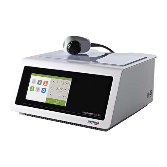
Description of controls and functional elements 1.4.1 ShockMaster 300 1. LCD TFT Touch Screen 2. Connector R-SW/V-ACTOR hand piece 3. V-Actor 1. Connector for R-SW hand piece / V-ACTOR... -
Page 12: Compressed Air Supply
1. USB connector (Type A) 2. Pressure filter housing 3. Mains connector 4. Mains fuse holder 5. Mains switch 6. Read the manual first NOTE The USB connection is only suitable for connecting a USB memory stick that supports the USB V1.1 protocol. Use only for service purposes! 1.4.2 Compressed air supply... -
Page 13: Installation
• Retain the original packaging. It may prove useful for any later equipment transport. Scope of Delivery The standard scope of supply for the ShockMaster 300 includes the following items: ShockMaster 300 control device • • Mains cable (EU / USA) •... -
Page 14: Installation
Installation 2.3.1 Hand piece / V-ACTOR securing installation The R-SW hand piece can be fitted on the right side of the system as desired by the • system user The V-Actor holder can be fitted on the left side of the system as desired by the system •... -
Page 15: Connecting The Power Cord
Insert the mains plug into the socket. • ATTENTION When setting up the instrument, make sure that the air outlets on the housing of the ShockMaster 300 is not blocked. The instrument must only be connected to properly earthed and correctly installed shockproof sockets. -
Page 16: Hand Piece Connection
Hand piece connection Connect the plug of the R-SW hand piece or V-ACTOR to the connector of the • ShockMaster 300. Ensure that the red dots on the connector match the red dots on the plug of the R-SW •... -
Page 17: Protective Measures Against Electrostatic Discharge (Esd)
Protective measures against electrostatic discharge (ESD) The following measures must be complied with during installations: Before creating an electrical connection, the housing of the medical product should be touched to discharge any electrostatic. Only use the accessories for this medical product that are listed in Chapter 6.2. Avoid any direct contact with freely exposed plug contacts or sockets, including the accessories of this medical product. -
Page 18: Operation
To avoid safety hazards, use of the instrument for applications other than those specified in chapter 1.1.1 INDICATIONS is not allowed! Do not use the ShockMaster 300 in potentially explosive environments, i.e. in the presence of a flammable anaesthetic mixture with air or with oxygen or nitrous oxide. - Page 19 The ShockMaster 300 must neither be deployed nor stored together with other devices. If the operation near or jointly with other devices is required, the ShockMaster 300 must be tested in that particular environment to ensure operation according to technical specification.
-
Page 20: Operation
NOTE The ShockMaster 300 meets the requirements of the applicable electromagnetic compatibility (EMC) standards EN60601-1-2. These limits are designed to provide reasonable protection against harmful interference in a typical medical installation. The instrument described here generates and uses high-frequency energy and can emit the same. If not installed and used in accordance with these instructions, the instrument may cause harmful interference with other devices in the vicinity. - Page 21 Control button to activate the “Indications List” screen Control button to activate the “Classic Indications” screen Control button to activate the “Myofascial Indications” screen Control button to activate the “Sports Indications” screen Control button to activate the “Body Area” screen Control button to activate “Settings”...
- Page 22 3.2.1.2 Treatment/Home screen The treatment screen consists of 2 parts. The parameters are shown on the right-hand side of the treatment screen. You can upload a pre-programmed set of parameters from the list of indications (please check chapter 3.2.1.3 Indication lists) For each indication there is a picture of the treatment.
- Page 23 3.2.1.2.1 Parameters The following parameters can be set: Pressure: 1–4 bar Adjustable by steps of 0.1 bar Number of 1-9.900 shocks adjustable by steps of: shocks: - 1 shock between 1-10 shocks - 10 shocks between 10-100 shocks - 100 shocks between 100-9.900 shocks >9.900 appears = unlimited amount of shocks Frequency:...
- Page 24 3.2.1.2.2 Treatment pictures of an uploaded indication When loading a pre-programmed indication the corresponding picture will show up on the left- hand side of the treatment screen. Pre-programmed indication picture: Treatment area is marked in blue • • 1/3 indicates the first of 3 sequences in total for the particular pre-programmed indication For example: Sequence 1-2-3...
- Page 25 The preferred applicator will be shown in the left-hand corner of the picture. If you press on the applicator’s picture field, the name of the applicator will appear. The name of the chosen indication will appear in the top left-hand corner. If the name is too long it will be not be shown completely unless you press on the name field.
- Page 26 Info: This screen will provide you with more detailed treatment information about the selected indication. The info is divided in the numbers of sequences for the selected indication. Every sequence provides information about: Title of the sequence Treatment information Parameter settings Treatment pictures (the number indicates the number of pictures for that sequence) Preferred (and alternative) applicator...
- Page 27 Filter function The “filter” button is located bottom corner. In order to find a certain type of indication more quickly, it is possible to show/hide every type of indication. You can select a filtered list by selecting the specific type of indication in the main menu or via the filter panel in the indication menu.
- Page 28 3.2.1.4 Body area The “Body Area” menu . The buttons are linked to several body areas. Each body area contains several indications. After selecting a body area, a pop-up screen will appear. For example press the Shoulder button: Each indication is supported with an anatomical image related to the indication’s muscle area. Select the desired indication, and press or double tap on the name of the indication.
- Page 29 3.2.1.5 Settings menu Functionality of the setting menu: Info: • Software version − Hardware type numbers − − Total shock counter • Language: The country specific language is selected in the basic settings and subsequently confirmed by pressing the button. −...
- Page 30 3.2.1.6 Software update Step 1: Start up the device. Step 2: Insert the USB stick with the correct data Step 3: Follow the instructions appearing on the screen Step 4: Check that you have loaded the correct version Go to the “Setting menu” and select “info”. On the screen is indicated: Software version X...
-
Page 31: Start-Up
Prior to start-up, please refer to the separate operating manual for your R-SW hand piece or V-ACTOR. Switch on the ShockMaster 300 at the mains switch on the rear of the instrument. • Once the instrument has been started, the display automatically shows 1.5 bar, 2000 •... - Page 32 Set the energy of the shocks to an initial value of 1.5 bar by using the plus or minus • button on the screen next to the value of bar. The value is shown on the pressure display. • The maximum application pressure is limited to 4 bars. To ensure correct system •...
-
Page 33: Functional Checks
Functional checks Perform the following functional checks after the instrument has been installed: Check the control device and hand piece for damage. • Put the ShockMaster 300 into operation (chapter 3.3 START-UP). • Set the pressure to 1.5 bars. •... -
Page 34: Treatment
Treatment CAUSION! Read chapter 3.1 GENERAL WARNINGS AND SAFETY INFORMATION before beginning treatment. Please also follow the instructions in the separate operating manual for your hand piece. Each time after the instrument has been transported, make sure that all functional checks have been performed on the instrument before you start treatment. - Page 35 CAUTION! The hand piece may not be operated while idling (without an impact surface). Do not trigger pulses unless the shock transmitter is in contact with the treatment zone!
-
Page 36: Cleaning, Maintenance And Overhaul
Cleaning, Maintenance and Overhaul Cleaning Regular cleaning of the system ensures perfect hygiene and operation of the ShockMaster 300. CAUTION Disconnect the unit and the accessories from the mains before starting any cleaning and overhauling work! Wipe the exterior of the housing with a damp cloth. -
Page 37: Replacement Mains Fuse
Replacement mains fuse The mains fuse holder is located on the rear panel of the ShockMaster 300. Push the clip of the mains fuse holder upwards and take the holder off the housing. • Pull the old fuses out of the mains fuse holder. -
Page 38: Replacing The Filter Element
Switch off the instrument at the mains switch on the rear and disconnect the mains • plug. It is easier to change the filter if you place the ShockMaster 300 upside down. First, • make sure that no condensation has collected in the filter housing. - Page 39 First, remove this securing screw with the aid of a cross point screwdriver (size PH2). • Then remove the complete filter element with the two black air current control rings • and the fixing screw. Take the filter element replacement kit and remove the new filter element, which is •...
-
Page 40: Maintenance
For further details on content and performance of the safety checks please contact your local dealer. The following checks should be performed to ensure that the ShockMaster 300 operates safely: Earth leakage current test in accordance with national regulations. •... -
Page 41: Repair
Uniphy Elektromedizin. Only original Uniphy Elektromedizin spare parts may be used for this purpose. Service life The average expected service life is approximately 10 years for the ShockMaster 300. For information about the service life of your hand piece, please refer to the separate operating manual for your hand piece. -
Page 42: Trouble Shooting
Trouble shooting Trouble shooting CAUTION Unplug the mains cable from the instrument before you carry out any maintenance work! Fault description Possible cause Corrective actions System does not work Power failure Check the power supply Defective mains fuse Replace the fuses Defective mains cable Replace the mains cable No compressed air supply... -
Page 43: Accessories And Spare Parts
• Gymna ShockMaster Registration Card Club • Patient Flyer Gymna ShockMaster - set of 25 • Gymna ShockMaster 300 User Manual – E (CD-ROM) • Contact Gel-500ml (conformity assessment accessory) • Protective anti skid mat *Standard accessories can differ from each distributor. Please contact your distributor for more information. -
Page 44: Documentation
Poster Gymna ShockMaster - 50x70cm • Gymna ShockMaster Certificate Treatment Centre • Gymna ShockMaster Registration Card Club • Gymna ShockMaster 300 User Manual – E Documentation • ShockMaster 300 user manual Accessory instruction R-SW Hand piece • Accessory instruction V-ACTOR (optional) -
Page 45: Technical Specifications
Technical Specifications ShockMaster 300 • R-SW operating mode R-SW single shock, continuous shock 0,5 – 17 Hz • Operating mode V-Actor single shock, continuous shock 0,5-31 Hz • R-SW energy selection 1 – 4 bar in steps of 0.1 bar •... -
Page 46: Identification Plate Shockmaster 300
Identification plate ShockMaster 300 Conformity with directives The device complies with the essential requirements of the Medical Devices Directive (93/42/EEC) and the Waste Electrical and Electronic Equipment Directive (2003/108/EC) of the European Parliament and of the Council as most recently changed. - Page 47 Guidance and manufacturer’s declaration – electromagnetic emissions The model ShockMaster 300 is intended to use in the electromagnetic environment specified below. The customer or the user of the ShockMaster 300 should assure that it is used in such an environment. Emissions test...
- Page 48 Guidance and manufacturer’s declaration – electromagnetic immunity The model ShockMaster 300 is intended to use in the electromagnetic environment specified below. The customer or the user of the ShockMaster 300 should assure that it is used in such an environment.
- Page 49 The model ShockMaster 300 is intended to use in the electromagnetic environment specified below. The customer or the user of the ShockMaster 300 should assure that it is used in such an environment. Emissions IEC 60601 test Electromagnetic environment -...
- Page 50 HF transmitters, an electromagnetic site survey should be considered. If the measured field intensity at the location in which the ShockMaster 300 is used exceeds the applicable HF compliance level indicated above, the ShockMaster 300 should be observed to verify normal operation.
- Page 51 ShockMaster 300 The ShockMaster 300 is intended for use in an electromagnetic environment in which radiated HF disturbances are controlled. The customer or the user of the ShockMaster 300 can help prevent electromagnetic interference by maintaining a minimum distance between...
-
Page 52: Warranty And Service
Warranty and service Warranty ATTENTION Modifications to the instrument or hand piece are not permitted. Any unauthorised opening, repair or modification by unauthorised personnel will relieve the manufacturer of its liability and responsibility for safe system operation. This will automatically void the warranty even before the end of the warranty period. 8.1.1 Warranty for the control device GymnaUniphy and the local GymnaUniphy dealer declares itself to be solely responsible for the... -
Page 53: Service
Service Should you have any further questions or require additional information, please feel free to contact your authorised service distributor. They will also give advice on questions regarding the implementation of technical inspections in accordance with your user responsibilities. When in doubt, contact the manufacturer or the worldwide distributors as listed on page 3. - Page 54 GymnaUniphy NV Pasweg 6A 3740 Bilzen Belgien T +32(0)89 510.510 F +32(0)89 510.511 info@gymna.com www.gymna.com Version 3.1 (2015-05-13)
Need help?
Do you have a question about the ShockMaster 300 and is the answer not in the manual?
Questions and answers