Advertisement
Quick Links
PN 292-120
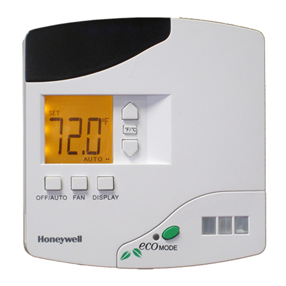
E529.RF Thermostat
Installation Guide
The e529.RF battery-
operated thermostat is
designed to work in
conjunction with an
HVAC controller to
monitor and maintain
room temperature (other
devices may also be
controlled from the
e529.RF).
There are three general
scenarios for using the e529.RF:
A basic IRAS application with the e529.RF
communicating wirelessly to another device
An IRAS application with RF communication
to a network backbone
An IRAS application with wired
communication to a network backbone
Installation
CAUTION!
!
The e529.RF is intended for indoor use only.
The E529.RF installer must be a trained,
experienced service technician.
All wiring must comply with local codes and
ordinances.
Failure to follow the instructions provided with the
product could damage the product or cause a
hazardous condition.
Placement
Without the need for power input, the e529.RF
affords great placement options for optimal
performance with virtually any fan coil unit, heat
pump, or packaged terminal air conditioner found in
guestrooms.
Since RF is critical to the e529.RF's operation,
placement of the device and careful consideration of
possible sources of radio interference are important.
For instance, the unit should not be placed close to
floor or ceiling or near pipe or other metal pieces.
Copyright 2013 INNCOM by Honeywell
To minimize external conditions interference with
room temperature measurement, locate the e529.RF
away from external doors or windows and areas in
direct sunlight.
Mounting Instructions
Separate the e529.RF
body and the
mounting plate by
pulling the bottom of
the mounting plate
away from the
e529.RF body and
then pull the mounting
plate down.
NOTE: If the back-
mounting plate is rotated more than 2 or 3
degrees, the plastic tabs at the top of the plate
may fracture or break off.
Attach the mounting plate to the wall or
electrical box with the arrow embossed on
the mounting plate pointing upward.
The e529.RF is provided with four 6-32 ¾"
sheet metal screws for mounting the plate to
an existing 4" × 4" electrical box. If attaching
the mounting plate to sheetrock or a similar
wall surface, install four 6-8 × ¾ anchors. The
four holes on the mounting plate can be used
to mark the location for the anchors.
Install the four AA alkaline batteries (NOTE:
Use alkaline batteries only) provided into the
battery compartment located on the rear of
the e529.RF. Depress the battery clamp latch
at the top of the battery compartment and
then swing open the battery clamp. Insert the
4 AA alkaline batteries, matching the "+"
terminals on the batteries to the "+" symbols
in the battery compartment. Close the battery
clamp and verify the latch is securely
fastened.
Verify that the e529.RF display is now
showing information. If the display is blank,
verify that the batteries are completely
installed with the right polarities and that the
batteries are not dead.
Advertisement

Related Manuals for Honeywell E529.RF


Summary of Contents for Honeywell E529.RF
- Page 1 An IRAS application with wired the mounting plate pointing upward. communication to a network backbone The e529.RF is provided with four 6-32 ¾” Installation sheet metal screws for mounting the plate to an existing 4” × 4” electrical box. If attaching...
-
Page 2: Service Mode
Installation Technicians. The entry below is provided Enter the LO 2-digit value (0–99). On pressing DISPLAY, the new rId will scroll across the LCD, then the e529.RF solely for informational purposes. The list of local parameters returns to the menu list below will change and grow. -
Page 3: Commissioning Process
NVRAM of parameter) partner devices. Activity in the NVRAM space P6: Set the e529.RF local address (default is 13) can severely affect functionality. This parameter should be used only by INNCOM technicians. P7: Set the P5 channel (default channel is 1) Commissioning Process P8: Set P5 partner (default partner is e528.36_X529.RF) -
Page 4: Fcc Statement
1. Use the PING parameter to test each device on the network. 2. Verify that e529.RF LCD displays a dot in lower right corner of the screen indicating RF link to HVAC partner. 3. Enter the RUN menu value 2. Execute a test of the IWAN. - Page 5 PN 292-120...
Need help?
Do you have a question about the E529.RF and is the answer not in the manual?
Questions and answers