
Related Manuals for HAAS + SOHN HSP 7 Diana 450.08


Summary of Contents for HAAS + SOHN HSP 7 Diana 450.08
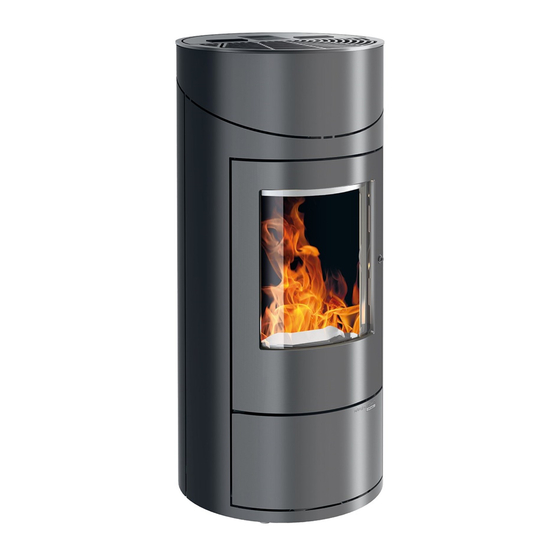
- Page 1 Equipment sheet HSP 7 Diana 450.08 HSP 7 Diana 450.08 Equipment sheet Pellet stove 0545008071403c...
- Page 2 Notes in the text Of utmost importance there are the notes entitled WARNING. The notes entitled WARNING advise you on serious danger of damage to the heating device or of an injury. The note entitled Notice advises you on possible damage to your heating device. The note entitled Important calls your attention to the information important for the operation of your heating device.
-
Page 3: Table Of Contents
4.2. Cleaning the pellet container - annual maintenance ............10 4.3. Cleaning of the ash pan - once a week................. 10 5. Replacement parts list......................11 5.1. Replacement parts list HSP 7 Diana 450.08 ............... 11 5.2. Detail A1............................ 14 6. Circuit diagram .......................... 15... -
Page 5: Technical Data
1. Technical data HSP 7 Diana 450.08 Heat output range: 2,4 – 8,2 kW Nominal heat output: 8,0 kW Height: 1053 mm Width: 494 mm Depth: 494 mm Weight: 125 kg Diameter of flue elbow: 80 mm Flue gas temperature: 197 °C... -
Page 6: Dimensions
2. Dimensions... -
Page 7: Cleaning Work
3. Cleaning work WARNING Before starting any cleaning work, the stove must be cool down! Once the cleaning work is completed, the correct operating status of the device must be re- established: Put the combustion pot in correctly, close the combustion chamber door. 3.1. - Page 8 WARNING If this is not done, the clinker will continue to accumulate. Then the device will no longer be able to ignite properly. Pellets can pile up in the combustion pot. In extreme cases, this can reach all the way back to the pellet chute.
-
Page 9: Maintenance Work
4. Maintenance work WARNING Before starting any cleaning work, the stove must be cool down! The mains plug must be pulled out of the power supply socket (always in advance)! The frequency of maintenance in turn depends to a large extent on the pellet quality (ash content). Quality pellets have a low ash content of about 0.2-0.3%. - Page 10 Figure 1: Removing the flue baffle...
- Page 11 Figure 2: Removing the cleaning cover...
- Page 12 Figure 3: Removing the side wall...
- Page 13 Figure 4: Shake the turbulator • For cleaning the flue gas passes, shake the turbulator 5 times at least, in compliance with the Fig. 4, pos. 4.
-
Page 14: Cleaning The Pellet Container - Annual Maintenance
4.2. Cleaning the pellet container - annual maintenance • Heat the pellet stove until the storage tank is completely empty. • Then the protective grille (1) in the pellet tank may be removed. • Then clean the tank and the intake of the screw conveyor housing with a vacuum cleaner. •... -
Page 15: Replacement Parts List
5. Replacement parts list 5.1. Replacement parts list HSP 7 Diana 450.08... - Page 16 Description Spare part number Pos. Piece Replacement parts list HSP 7 Diana 450.08 Complete combustion chamber door/black 1 piece 0545008005300 Ash door panel/black 1 piece 0545008015330 Ash door panel/grey 1 piece 0545008025330 Cleaning cover front/black 1 piece 0545008005037 Seal for cleaning cover 8 mm (620 mm)
- Page 17 Suction flange 1 piece 0545008105335 Seal for suction flange 1 piece 0545008007333 Flue gas thermosensor 1 piece 0553808005540 Ignition 1 piece 0541908005202 Lighter case 1 piece 0545008105220 Room temperature sensor 1 piece 0089500390005 1 piece 0089500080005 Induced draught fan 1 piece 0561008005807 1 piece Air inlet funnel...
-
Page 18: Detail A1
5.2. Detail A1 Description Spare part number Pos. Piece Detail A1 Screwing door - Set 1 piece A1.1. 0545008005221 1 piece A1.2. Glass holder/black - Set 0545008005222 1 piece Combustion chamber door/black Seal glass 8x2 mm (1340 mm) 1 piece 0040208020005 Door glass 1 piece... -
Page 19: Circuit Diagram
6. Circuit diagram Circuit diagram IO 33.3... - Page 20 Description Circuit diagram: No.: Description Cable harness Mains plug / mains filter Electric ignition Screw conveyor motor Induced draught Flue gas temperature sensor 35/36 Flame temperature sensor 37/38 Room temperature sensor 39/40 Bottom flame temperature sensor 41/42 43/44 Door contact switch Flue gas fan rotation speed 48-50 Fuse T 3,15 A ignition, induced draught fan, screw...
Need help?
Do you have a question about the HSP 7 Diana 450.08 and is the answer not in the manual?
Questions and answers