Table of Contents
Advertisement
Quick Links
CB650M-BX(1,2¿Â) 00.5.12 2:8 PM ∆‰¿Ã¡ˆ1
Federal Communications Commission Statement
This equipment has been tested and found to comply with the limits for a
Class B digital device, pursuant to part 15 of the FCC Rules. These limits are
designed to provide reasonable protection against harmful interference in a
residential installation. This equipment generates, uses and can radiate radio
f requency energy and, if not installed and used in accordance with the
i n s t ructions, may cause harmful interference to radio communications.
H o w e v e r, there is no guarantee that interference will not occur in a particular
installation. If this equipment does cause harmful interference to radio or
television reception, which can be determined by turning the equipment off
and on, the user is encouraged to try to correct the interference by one or more
of the following measures :
- Reorient or relocate the receiving antenna.
- Increase the separation between the equipment and re c e i v e r.
- Connect the equipment into an outlet on a circuit diff e rent from that to which
the receiver is connected.
- Consult the dealer or an experienced radio/TV technician for help.
Changes or modifications not expressly approved by the party responsible
for compliance could void the user's authority to operate the equipment.
CB650M-BX Mother Board
1
Advertisement
Table of Contents

Related Manuals for Daewoo CB650M-BX

Summary of Contents for Daewoo CB650M-BX
- Page 1 CB650M-BX(1,2¿Â) 00.5.12 2:8 PM ∆‰¿Ã¡ˆ1 CB650M-BX Mother Board Federal Communications Commission Statement This equipment has been tested and found to comply with the limits for a Class B digital device, pursuant to part 15 of the FCC Rules. These limits are designed to provide reasonable protection against harmful interference in a residential installation.
-
Page 2: Table Of Contents
CB650M-BX(1,2¿Â) 00.5.12 2:8 PM ∆‰¿Ã¡ˆ2 CB650M-BX Mother Board Table of Contents Table of Contents 1. Introduction Overview••••••••••••••••••••••••••••••••••••••••••••••1-1 Main Features ••••••••••••••••••••••••••••••••••••••••••1-2 Motherboard Layout ••••••••••••••••••••••••••••••••••••• 1-8 2. Installation Check List••••••••••••••••••••••••••••••••••••••••••••• 2-1 Installation Steps •••••••••••••••••••••••••••••••••••••••• 2-1 Set Jumpers•••••••••••••••••••••••••••••••••••••••••••• 2-2 1. Processor Core:BUS Frequency Multiple •••••••••••••••• 2-2 2. - Page 3 CB650M-BX(1,2¿Â) 00.5.12 2:8 PM ∆‰¿Ã¡ˆ3 CB650M-BX Mother Board 9. Power Switch connector ••••••••••••••••••••••••••• 2-12 10. Micro ATX Power Supply connector•••••••••••••••••• 2-13 11. Telephony(TDA) connector •••••••••••••••••••••••• 2-13 12. Aux-In(Line-In) connector••••••••••••••••••••••••• 2-13 13. CD-ROM(Panasonic) Audio connector •••••••••••••••• 2-14 14. ATAPI Audio connector •••••••••••••••••••••••••• 2-14 External connectors •••••••••••••••••••••••••••••••••••••...
-
Page 4: Introduction
1. Introduction Overview The CB650M-BX motherboard integrates the latest advances in pro c e s s o r, m e m o r y, and I/O technologies into a Micro ATX form factor(244x205mm) that combines performance, flexibility, and easy of use into high integrated capable of meeting a variety of price/performance levels. -
Page 5: Main Features
Main Features 1. Processor : The CB650M-BX motherboard supports a single Pentium II/III or Celero n p ro c e s s o r. The pro c e s s o r’s VID pins automatically program the voltage regulator on the motherboard to the re q u i red processor voltage. The host bus speed(66MHz or 100MHz) is automatically selected. - Page 6 CB650M-BX(1,2¿Â) 00.5.12 2:8 PM ∆‰¿Ã¡ˆ1-3 CB650M-BX Mother Board PCI bus interface Data Buff e r i n g Power management functions Compliant with ACPI power management SMBus support for desktop management functions Support for system management mode(SMM) 2-2. 82371EB PCI ISA IDE Xcelerator(PIIX4E)
- Page 7 Demultiplexing of address and data on the bus for nearly 100% bus eff i c i e n c y 4. USB The CB650M-BX motherboard has two USB ports;one USB peripheral can be connected to each port. The two USB ports are implemented with stacked back panel I/O connectors.
- Page 8 CB650M-BX(1,2¿Â) 00.5.12 2:8 PM ∆‰¿Ã¡ˆ1-5 CB650M-BX Mother Board 6. Real-Time Clock, CMOS RAM, and Battery The real-time clock is compatible with DS1287 and MC146818 components. The clock provides a time-of-day clock and a multi-century calendar with alarm features and century ro l l o v e r. The real-time clock supports 256 bytes of battery-backed CMOS SRAM in two banks that are reserved for BIOS use.
- Page 9 CB650M-BX(1,2¿Â) 00.5.12 2:8 PM ∆‰¿Ã¡ˆ1-6 CB650M-BX Mother Board 7-3. Diskette Drive Contro l l e r The I/O controller support two diskette drive that is compatible with the 82077 diskette drive controller and support both PC-AT and PS/2 modes. 7-4. Keyboard and Mouse Interf a c e PS/2 keyboard and mouse connectors are located on the back panel.
- Page 10 CB650M-BX(1,2¿Â) 00.5.12 2:8 PM ∆‰¿Ã¡ˆ1-7 CB650M-BX Mother Board When suggested ratings for temperature, fan speed, or voltage are exceeded, an interrupt is activated. 10. Wake on LAN Technology Wake on LAN technology enables remote wakeup of the computer through a network.
-
Page 11: Motherboard Layout
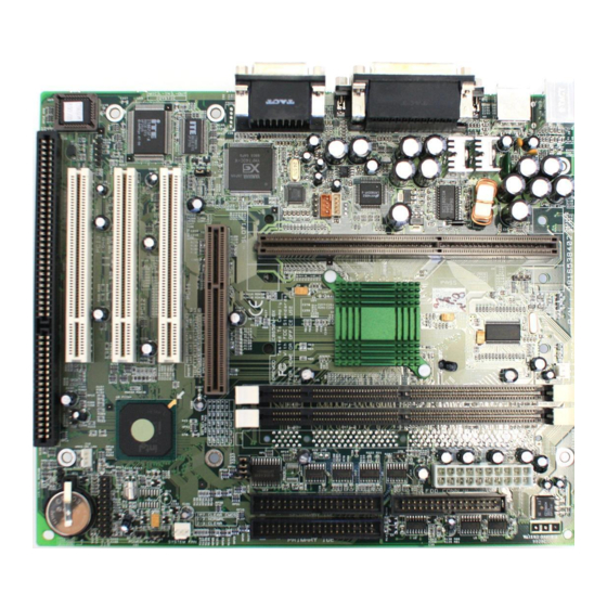
CB650M-BX(1,2¿Â) 00.5.12 2:8 PM ∆‰¿Ã¡ˆ1-8 CB650M-BX Mother Board Motherboard Layout Figure 1. CB650M-BX Motherboard Layout 1 - 8... -
Page 12: Installation
Chapter 2. 2. Installation 2. Installation This Chapter provides information how to install and configure the CB650M-BX m o t h e r b o a rd . Check List The standard packing of the C B 6 5 0 M - B X should include :... -
Page 13: Set Jumpers
CB650M-BX(1,2¿Â) 00.5.12 2:8 PM ∆‰¿Ã¡ˆ2-2 CB650M-BX Mother Board Set Jumpers Several hard w a re settings are made through the use of jumper cap to connect jumper pins on the motherboard. See motherboard layout on page 1-8 for location of jumpers. The jumper settings will be described numerically such as '1-2', '2-3' or 'On(Short)', 'Off ( O p e n ) ' . -
Page 14: Disable Onboard Audio
CB650M-BX(1,2¿Â) 00.5.12 2:8 PM ∆‰¿Ã¡ˆ2-3 CB650M-BX Mother Board Clear CMOS Normal Clear 3. Disable Onboard Audio(JP9) This jumper uses for Enable or Disable the onboard audio subsystem. Internal Audio Enable(Default) Disable Warning! Computer motherboards and Add-on cards contain very delicate IC chips. -
Page 15: Installing The System Memory
1. General DIMM Notes For the Host bus to operate at above 100MHz, use only PC100-compliant DIMMs. The CB650M-BX motherboard operates at 100MHz, thus most systems will not even boot if non-compliant modules are used because of the strict timing issues involved under this speed. If your DIMMs are not PC100-compliant, set the Host bus frequency to 66MHz for the system s t a b i l i t y. -
Page 16: Installing And Removing Dimms
CB650M-BX(1,2¿Â) 00.5.12 2:8 PM ∆‰¿Ã¡ˆ2-5 CB650M-BX Mother Board 3. Installing and Removing DIMMs To install the DIMMs, locate the memory banks on the motherboard and perform the following steps : 1. Hold the DIMM so that notched edge is aligned with the notch on the DIMM s o c k e t ( F i g u re 2-1). -
Page 17: Installing The Pentium Ii/Iii Processor
CB650M-BX(1,2¿Â) 00.5.12 2:8 PM ∆‰¿Ã¡ˆ2-6 CB650M-BX Mother Board A URM is supplied to anchor the processor to the motherboard. Attach the URM before inserting the pro c e s s o r. Installing the Pentium II/III processor 1. Installing the URM... -
Page 18: Installing A Processor
CB650M-BX(1,2¿Â) 00.5.12 2:8 PM ∆‰¿Ã¡ˆ2-7 CB650M-BX Mother Board Figure 2-3. Installing the URM Kit 2. Installing a Processor Follow the steps below to install the Pentium II/III pro c e s s o r : 1. Locate the Slot 1 connector. -
Page 19: Processor Installation Overview
CB650M-BX(1,2¿Â) 00.5.12 2:8 PM ∆‰¿Ã¡ˆ2-8 CB650M-BX Mother Board 4. Lock the base into place by inserting a pin down into the base on the both s i d e s . 5. Gently insert the processor cartridge down into the URM, making sure the connector on the processor cartridge and Slot 1 connector are aligned. -
Page 20: Installing A Processor(Boxed Version)
CB650M-BX(1,2¿Â) 00.5.12 2:8 PM ∆‰¿Ã¡ˆ2-9 CB650M-BX Mother Board 3. Installing the Processor (Boxed version) A boxed version of the Processor is off e red through Intel. This packing uses an active cooling fan. The mounting hard w a re is described below. For detailed i n s t ructions, please refer to the documentation that is supplied with your P ro c e s s o r. -
Page 21: Installing Cables
4. IR connector (J19) CB650M-BX provides one connector which can support IrDA (InfraRed Data Association) receiver module. It gives users IR wireless data exchange dire c t l y f rom mobile computers, printers and PDAs,...etc. -
Page 22: Wake On Lan Connector
CB650M-BX(1,2¿Â) 00.5.12 2:8 PM ∆‰¿Ã¡ˆ2-11 CB650M-BX Mother Board 5. Wake on LAN connector (J16) This connector supports Wake on LAN function. If you use Wake on LAN function, connect 3-pin cable between this connector and your LAN Card . Signal Name +5V STBY 6. -
Page 23: Secondary Fan Connector
CB650M-BX(1,2¿Â) 00.5.12 2:8 PM ∆‰¿Ã¡ˆ2-12 CB650M-BX Mother Board POWER LED K B D (1 color) L O C K S P E A K E R A C P I H D D H / W POWER LED B T #... -
Page 24: Micro Atx Power Supply Connector
CB650M-BX(1,2¿Â) 00.5.12 2:8 PM ∆‰¿Ã¡ˆ2-13 CB650M-BX Mother Board 10. Micro ATX Power Supply Connector (J22) This connector connects to an Micro ATX power supply. The plug from the power supply will only insert in one orientation because of the diff e rent hole- size. -
Page 25: Cd-Rom(Panasonic) Audio Connector
External Connectors 1. PS/2 Keyboard & Mouse Connector (J9) The CB650M-BX provides one PS/2 keyboard and one PS/2 mouse connector. Refer to the Figure 2-7 for the direction of keyboard (mouse) cable to install on k e y b o a rd (mouse) connector. - Page 26 PC peripheral expansion. A single USB port can be connect up to 127 peripheral devices, such as mice, modems, and keyboards. USB also supports Plug-and- Play and Hot plugging. The CB650M-BX provides 2 channel USB ports. Figure 2-7. External connectors 5.
-
Page 27: Installing Sound Driver
Installing sound driver 1. Overview CB650M-BX motherboard uses Yamaha YMF740C/724F chipset for PCI audio. This controller supports 32-voice XG wavetable synthesizer, Dire c t S o r n d h a rd w a re Acceleration, Downloadable Sound and DirectMusic acceleration. - Page 28 CB650M-BX(1,2¿Â) 00.5.12 2:8 PM ∆‰¿Ã¡ˆ2-17 CB650M-BX Mother Board • To install driver for Windows NT or DOS, run the setup in the each folder and follow the steps of the setup pro g r a m . 2 - 1 7...
Need help?
Do you have a question about the CB650M-BX and is the answer not in the manual?
Questions and answers