Advertisement
Quick Links
TECHNICALMANUALS
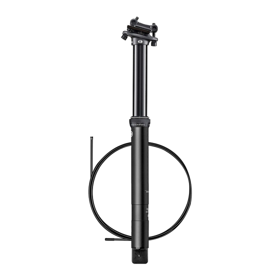
Highline Refresh Kit Contents: Part No. 99151
parts + accessories
x2
Igus Guide
Blocks
x1
x1
Upper Igus Bearing
x1
Seal / Collar
Assembly
Lower Igus Bearing
Highline Seatpost
450 Hour Maintenance / Overhaul
Tool List:
Shop Rag
24mm Open Face Wrench
2.5mm Hex Key
3mm Hex Key
5mm Hex Key
Tape
Loc-tite 242
Highline Refresh Kit (99151)
Box Cutter
Rubber (optional)
x1
Grease Packet
Rev. A - 3.7.18
1/18
Advertisement

Related Manuals for Crankbrothers Highline Seatpost


Summary of Contents for Crankbrothers Highline Seatpost
- Page 1 Highline Seatpost TECHNICALMANUALS 450 Hour Maintenance / Overhaul Rev. A - 3.7.18 Tool List: Shop Rag 24mm Open Face Wrench 2.5mm Hex Key 3mm Hex Key 5mm Hex Key Tape Loc-tite 242 Highline Refresh Kit (99151) Box Cutter Rubber (optional) Highline Refresh Kit Contents: Part No.
- Page 2 Disassembly Prior to starting, note the saddle position on the rails and seatpost height in frame. Loosen the front and back bolts of the quick release head Swing the back bolt out of the slot assembly using a 5mm hex wrench. in the head of the quill, and then rotate the saddle forward to remove Remove the lower cradle, clean...
- Page 3 Turn the barrel adjuster in at the lever to remove cable tension. Using a 3mm hex wrench, unthread the remote lever clamp screw and open the lever’s hinge to remove it from the handlebars. Remove the cartridge screw from the top of the quill head using a 2.5mm hex wrench.
- Page 4 Slide the post out of the frame while pushing the housing through Apply a large piece of tape to the frame at the same time. the cable housing. This will hold the actuator housing lockring in place and prevent it from dropping into the frame when it is removed in the next step.
- Page 5 Using your hand, unthread the actuator housing lockring from the Wiggle and pull down on the Unthread the base cap of the bottom of the outer body. Do not use pliers for this step! If necessary, actuator housing to remove it seatpost using a 24mm or use a piece of inner tube to achieve better grip on the lockring.
- Page 6 Push down on the quill head to expose the cartridge for removal. Remove the bottom out O-ring from the cartridge or outer body. Wiggle and pull down on the cartridge to remove it from the quill. Clean and set aside. You may experience some resistance which is normal.
- Page 7 Unthread the seal ring assembly Pull the quill assembly out of the Using a flat blade knife, gently Remove the lower Igus bushing. from the outer body. If necessary, outer body. pry out both Igus keys from the use a piece of inner tube for channel and discard.
- Page 8 Remove the upper Igus bushing. Slide the seal ring assembly off Wipe off the quill and the inside of the outer body using a cleaning the quill and discard. rag. Never use solvents or degreasers on these parts in order to prevent damage to the anodized finish.
- Page 9 Assembly Prior to starting, make sure all parts are clean of dirt and debris. Gently install the new seal ring assembly. Be careful not to force the Using the provided grease (Slick Honey works as well) apply small seal over the lower bushing channel. Walk the seal lip over the edge amount to the lower bushing channel.
- Page 10 Apply a small amount of grease to the two key channels of the quill. Insert the new Igus keys into the channel and if necessary, tap lightly with a hammer to fully seat the keys into the groove. 10/18...
- Page 11 Using the remaining grease in the packet, coat evenly the lower surface of the quill, bushings and keys approximately 10mm above the keys. 11/18...
- Page 12 Alignment Channel Insert the quill assembly into the outer body. Be sure to align the Lower the seal ring on the quill Install the bottom out O-ring over Igus keys with the alignment channels inside the outer body before and lightly thread the assembly the cartridge and position evenly applying force.
- Page 13 Thread the cartridge base cap into the outer body; be careful not to Apply one drop of 242 (blue) threadlocker to the cartridge screw damage the bottom out O-ring. Tighten the base cap to 12 Nm using threads. Install the cartridge screw into the quill head and thread the 24mm or adjustable wrench.
- Page 14 Figure B Figure A Lightly grease the actuator O-ring. Align the actuator screw with the Lightly rotate the actuator body so the ledge on the actuator lines up cartridge valve adapter (figure A) and insert the actuator assembly into with the arrow on the base cap decal. Note: Adjusting the actuator the base cap of the seatpost by wiggling and pressing inward.
- Page 15 Thread the actuator lockring onto the base cap and tighten Insert the seatpost into the frame while simultaneously moving the firmly by hand. Make sure the actuator is locked into position cable housing in the same direction. Be sure to move them evenly and cannot move if twisted.
- Page 16 Tighten the seatpost collar per Position the upper cradle above the saddle rails. Place and hold the lower cradle on the quill head so that manufacturer’s instructions. the longer section of the cradle faces the rear of the bike. Rotate the saddle onto the lower cradle and swing Never exceed 7Nm! the back bolt into the slot of the quill head.
- Page 17 Secure the saddle into the position as noted prior to removal. Make Install the remote lever onto the Activate the remote lever and sure the cradle washers are aligned with the cupped section of the handlebar into the desired lower the saddle half way down. quill head.
- Page 18 While remaining compressed, tighten the seal ring assembly firmly by hand. If necessary, use a piece of inner tube for better grip on the collar. Do not use pliers for this step! Test the post for proper function. If you experience any malfunction, refer to our Troubleshooting Guidelines for assistance.
Need help?
Do you have a question about the Highline Seatpost and is the answer not in the manual?
Questions and answers