
Related Manuals for Taylor C2


Summary of Contents for Taylor C2
- Page 1 TAYLOR STUDWELDING SYSTEMS LIMITED OPERATING GUIDE CD STUDWELDING PISTOLS TYPE C2 & LG2 V-21A...
- Page 2 PAGE CONTENT GENERAL INFORMATION INTRODUCTION EXTERNAL FEATURES SAFETY SETTING UP AND WELDING WELD ASSESSMENT/TESTING METHODS OF STUD LOCATION COMPONENT EXPLOSION AND PARTS LISTING - C2 PISTOL COMPONENT EXPLOSION AND PARTS LISTING - LG2 PISTOL ACCESSORIES EC DECLARATION OF CONFORMITY V-21A...
-
Page 3: General Information
Please read this guide carefully before installation of the machine. Please especially observe the safety instructions. Taylor Studwelding Systems Limited reserves the right to amend the contents of this manual without notification. V-21A... - Page 4 INTRODUCTION INTRODUCTION Taylor Studwelding Systems Capacitor Discharge units are compact, portable Stud Welding equipment. The units are specifically designed to enable a small diameter range of ferrous and non-ferrous weld studs to be welded to light gauge, self-finish or pre-coated materials, in most cases with little or no reverse marking.
-
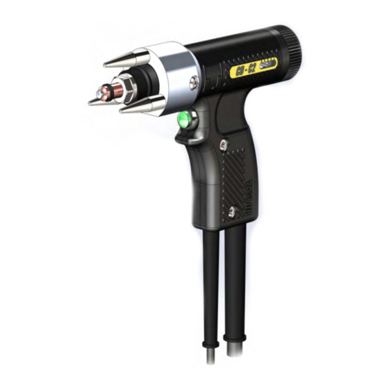
Page 5: External Features
EXTERNAL FEATURES C2 PISTOL LG2 PISTOL COMPLETE PISTOL ORDER NUMBER 99-100-010 99-100-011 FRONT END CAP ASSEMBLY* FRONT END CAP ASSEMBLY* CD CHUCK* CD CHUCK* CHUCK NUT CHUCK NUT TRIGGER PUSHBUTTON TRIGGER PUSHBUTTON WELDING PLUG WELDING PLUG CONTROL PLUG CONTROL PLUG... - Page 6 SAFETY PROTECT YOURSELF AND OTHERS ! These welding pistols whilst unconnected are inert but once connected as part of a complete welding installation may present potential risks and dangers. Please read and understand these safety notices. 1. ELECTRICAL No portion of the outer cover of the welding controller should be removed by anyone other than suitably qualified personnel and never whilst mains power is connected.
-
Page 7: Maintenance
Measures must be taken to prevent the use of this equipment by unauthorised personnel. Please note that Taylor Studwelding Systems Ltd also offer, at an additional cost, personnel training packages, should a certificate of competency be required for operating/maintenance personnel. - Page 8 "Capacitor Discharge Stock list" which can found by scanning the QR code below or alternatively is available from your local Taylor stockist. Select the required CD chuck for the chosen weld stud diameter (a list of available chucks is shown on page 30 of this guide), insert...
- Page 9 SETTING UP & WELDING At this point the pistol setting method differs dependent on the type of pistol being used: SETTING THE C2 TYPE PISTOL Set the pistol spring pre-load to the appropriate setting for the stud/ material to be welded. This is achieved by twisting the rear end cap adjuster.
- Page 10 SETTING UP & WELDING To do this place the pistol into the welding position, pressing down on the pistol until the stud is pressed back into the pistol and all three points of the tripod legs are firmly in contact with the work surface. With the pistol held firmly in this position.
- Page 11 CD controllers, including but not exclusive to those manufactured by Taylor Studwelding Systems Ltd. The type C2 pistol is a contact pistol and will work with most controllers given an appropriate connection profile whilst the type LG2 pistol is a lift gap pistol and must be paired with a suitable lift gap controller.
- Page 12 CONTACT PROCESS, TIME 0.000 0.001 0.002 0.003 TAKEN (s) - C2 Once welding has taken place. Draw the pistol off the welded stud. Always lift the welding pistol vertically from the welded stud. Failure to do this may cause...
- Page 13 SETTING UP & WELDING Visually inspect the weld. A good weld will result in an all round weld with a small visible witness of spatter surrounding the flange of the stud. A cold stud weld is noticeable by undercutting of the flange and lack of / minimal formation of spatter.
-
Page 14: Mechanical Tests
WELD ASSESSMENT/TESTING Visual examination of weld quality can, even with limited experience, provide a useful quality assessment. In such a check the presence of a small even witness of weld material around the base of the stud flange after welding should be ensured. Poor welds are indicated by excess metal on one side of the welded flange and/or the presence of an undercut or non-fused area between the stud flange and the parent sheet or plate. - Page 15 METHODS OF STUD LOCATION Economic stud location may be obtained using any one of the following methods, depending on the type of work involved :- • Tripod leg assembly. • Nose cone assembly. • Extended leg assembly. TRIPOD LEG ASSEMBLY. This is generally used for low volume production and one off components.
- Page 16 COMPONENT EXPLOSION AND PARTS LISTING PISTOL TYPE ITEM PART No. DESCRIPTION 71-101-030 CONTROL PLUG 71-300-010 CONTROL CABLE (per metre) 81-101-051 WELD PLUG 71-300-002 WELD CABLE (per metre) 71-101-032 CABLE CLIP (NOT SHOWN) V-21A...
- Page 17 COMPONENT EXPLOSION AND PARTS LISTING SEE PAGES XX FOR CHUCKS AND ACCESSORIES. ITEM QTY PART No. DESCRIPTION 79-101-052 TRIPOD LEG 79-101-051 FRONT END CAP Z115-05-006 SCREW 71-101-002 CHUCK NUT 71-101-004 BELLOWS RETAINING RING 71-101-202 BODY RING 71-101-203 REAR END CAP Z120-04-020 SCREW 71-101-003...
- Page 18 COMPONENT EXPLOSION AND PARTS LISTING ITEM QTY PART No. DESCRIPTION 71-101-200 PISTOL BODY MOULDING PAIR 71-101-217 DECAL STICKER Z250-10-019 SCREW PISTOL SCHEMATIC RED or BLUE 4 PIN TRIGGER SWITCH CONTROL BLUE or RED PLUG V-21A...
- Page 19 COMPONENT EXPLOSION AND PARTS LISTING SEE NEXT PAGE FOR SHAFT BREAKDOWN 13 14 ITEM PART No. DESCRIPTION 71-101-220 FLEXI-BRAID ASSEMBLY Z600-05-000 WASHER Z115-05-012 SCREW Z200-04-006 SCREW Z700-05-022 TERMINAL Z115-05-008 SCREW 71-101-201 TERMINAL PLATE 81-101-279 PUSHBUTTON SWITCH Z225-08-914 SCREW Z605-05-999 WASHER 71-101-214 CABLE CLIP 71-101-033...
- Page 20 COMPONENT EXPLOSION AND PARTS LISTING ITEM QTY PART No. DESCRIPTION 71-101-215 BEARING 71-101-204 BEARING HOUSING 71-101-205 SHAFT 71-101-014 SPRING 71-101-213 DETENT 71-101-207 ADJUSTER DRIVER Z800-04-026 BHAR PIN Z800-06-028 SAR PIN 71-101-206 PRE-LOAD ADJUSTER Z505-04-000 Z400-04-016 SCREW V-21A...
- Page 21 COMPONENT EXPLOSION AND PARTS LISTING PISTOL TYPE ITEM PART No. DESCRIPTION 71-101-030 CONTROL PLUG 71-300-009 CONTROL CABLE (per metre) 81-101-051 WELD PLUG 71-300-002 WELD CABLE (per metre) 71-101-032 CABLE CLIP (NOT SHOWN) V-21A...
- Page 22 COMPONENT EXPLOSION AND PARTS LISTING SEE PAGE XX FOR CHUCKS AND ACCESSORIES. ITEM QTY PART No. DESCRIPTION 79-101-052 TRIPOD LEG 79-101-051 FRONT END CAP Z115-05-006 SCREW 71-101-002 CHUCK NUT 71-101-004 BELLOWS RETAINING RING 71-101-232 BODY RING 71-101-203 REAR END CAP Z120-04-020 SCREW 71-101-003...
- Page 23 COMPONENT EXPLOSION AND PARTS LISTING ITEM QTY PART No. DESCRIPTION 71-101-200 PISTOL BODY MOULDING PAIR 71-101-218 DECAL STICKER Z250-10-019 SCREW PISTOL SCHEMATIC RED or BLUE GREEN or YELLOW 4 PIN TRIGGER SWITCH CONTROL YELLOW or GREEN PLUG BLUE or RED COIL V-21A...
- Page 24 COMPONENT EXPLOSION AND PARTS LISTING SEE NEXT PAGE FOR SHAFT BREAKDOWN 14 15 ITEM PART No. DESCRIPTION 71-101-220 FLEXI-BRAID ASSEMBLY Z600-05-000 WASHER Z115-05-012 SCREW Z200-04-006 SCREW Z700-05-022 TERMINAL Z115-05-008 SCREW 71-101-201 TERMINAL PLATE 81-101-279 PUSHBUTTON SWITCH Z225-08-914 SCREW Z605-05-999 WASHER 71-101-214 CABLE CLIP 71-101-033...
-
Page 25: Dowel Pin
COMPONENT EXPLOSION AND PARTS LISTING ITEM QTY PART No. DESCRIPTION 71-101-230 SPRING 71-102-071 BEARING 71-101-208 BEARING HOUSING 71-101-209 SHAFT 72-103-042 POLE PIECE 72-103-042 COIL 71-101-210 COIL MOUNT 71-101-213 DETENT 71-101-211 COIL MOVER 71-101-011 CIRCLIP Z800-04-026 DOWEL PIN 71-101-219 INDICATOR LABEL Z400-04-012 SCREW NOTE! THESE COMPONENTS ARE NOT AVAILABLE SEPERATELY. - Page 26 ACCESSORIES STANDARD TRIPOD LEG ASSEMBLY COMPLETE ASSEMBLY AVAILABLE UNDER PART NUMBER : 79-101-050 (STANDARD) NOTE # LONG LEGS ARE USED WHEN WELDING STUD LENGTHS BETWEEN 35 AND 50, OR WHEN WELDING M10 STUDS. ITEM DESCRIPTION PART No. TRIPOD LEG (STANDARD) 79-101-052 TRIPOD LEG (LONG.
- Page 27 ACCESSORIES SLIMLINE TRIPOD LEG ASSEMBLY COMPLETE ASSEMBLY AVAILABLE UNDER PART NUMBER : 79-101-060 (STANDARD) NOTE # LONG LEGS ARE USED WHEN WELDING STUD LENGTHS BETWEEN 35 AND 50, OR WHEN WELDING M10 STUDS. ITEM DESCRIPTION PART No. TRIPOD LEG (STANDARD) 79-101-062 TRIPOD LEG (LONG.
- Page 28 ACCESSORIES 79-101-274 79-101-275 EXTENDED LEG ASSEMBLY - MOUNTS ON STANDARD FRONT END CAP COMPLETE ASSEMBLIES AVAILABLE UNDER PART NUMBERS ABOVE STANDARD ASSEMBLIES (SEE TOP OF PAGE) HAVE EITHER THE PIN GUIDE OR THE NOSE CONE (ITEM 1) FITTED. IF BOTH ITEMS ARE REQUIRED THE ADDITIONAL PART MUST BE ORDERED SEPERATELY AS BOTH ITEMS ARE NOT SUPPLIED WITH AN ASSEMBLY AS STANDARD.
- Page 29 ACCESSORIES OFFSET CHUCK ADAPTOR COMPLETE ASSEMBLY AVAILABLE UNDER PART NUMBER : 79-101-110 NOSE CONE CENTERING DEVICE COMPLETE ASSEMBLIES AVAILABLE UNDER PART NUMBERS : Ø22 CUP & ROD 79-101-112 Ø25.4 (1”) CUP & ROD 79-101-113 Ø30 CUP & ROD 79-101-114 ITEM DESCRIPTION PART No.
- Page 30 ACCESSORIES STANDARD CD CHUCK C/W BACKSTOP PART NUMBERS : M2.5 79-101-002 79-101-003 79-101-004 79-101-005 79-101-006 M7.1 79-101-007 79-101-008 STANDARD M10 CHUCK C/W BACKSTOP PART NUMBER : 79-101-010 EARTH TAG CHUCK PART NUMBER : 79-101-019 LARGE BRACKET CHUCK PART NUMBER : 79-101-022 V-21A...
-
Page 31: Eu Declaration Of Conformity
West Yorkshire WF13 2BD Designation of Product : Studwelding equipment CDM series types CDM8, CDM9, CDM10 Studwelding gun series C1, C2, LG1, LG2 The above mentioned equipment complies with the requirements of the following directives : 93/68/EEC The CE Marking Directive...
Need help?
Do you have a question about the C2 and is the answer not in the manual?
Questions and answers