
Related Manuals for Taylor DA4


Summary of Contents for Taylor DA4
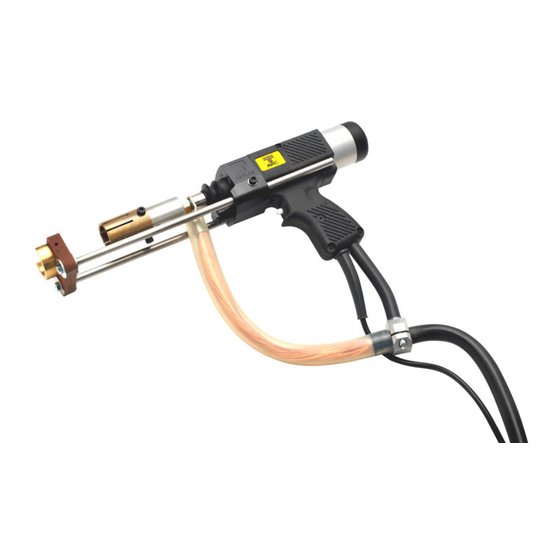
- Page 1 TAYLOR STUDWELDING SYSTEMS LIMITED OPERATING GUIDE FOR TYPES DA4, DA5 & DA6 HI-LIFT DRAWN ARC PISTOL V-21A A TAYLORMADE DRAWN ARC STUDWELDING PISTOL...
- Page 2 INDEX PAGE No. CONTENT USEFUL INFORMATION. IMPORTANT SAFETY INFORMATION. INTRODUCTION TO STUDWELDING. SETTING UP AND WELDING. EXPLODED DIAGRAMS AND PARTS LISTINGS. ACCESSORIES. EC DECLARATION OF CONFORMITY. V-21A...
-
Page 3: Useful Information
USEFUL INFORMATION MANUFACTURERS DETAILS TAYLOR STUDWELDING SYSTEMS LIMITED COMMERCIAL ROAD DEWSBURY WEST YORKSHIRE WF13 2BD ENGLAND TELEPHONE +44 (0)1924 452123 FACSIMILE +44 (0)1924 430059 email sales@taylor-studwelding.com www.taylor-studwelding.com SALES DIRECT TEL +44 (0)1924 487703 TECHNICAL HELPLINE : +44 (0)1924 487701 You may wish to record the details of your controller below as this information will help with any technical assistance you may require: PISTOL SERIAL No. - Page 4 PRODUCED DURING NORMAL USE, THIS PISTOL MUST ONLY BE OPERATED IN AN INDUSTRIAL ENVIRONMENT. NEVER REMOVE ANY PORTION OF THE PISTOL HOUSING WITHOUT FIRST ISOLATING THE PISTOL FROM THE CONTROLLER. Taylor Studwelding Systems Limited reserves the right to amend the contents of this guide without notification. V-21A...
-
Page 5: Important Safety Information
IMPORTANT SAFETY INFORMATION ! PROTECT YOURSELF AND OTHERS ! Read and understand these safety notes. 1. ELECTRICAL No portion of the outer cover of the welding controller should be removed by anyone other than suitably qualified personnel and never whilst mains power is connected. ALWAYS DISCONNECT THE MAINS LEAD BEFORE ATTEMPTING ANY MAINTENANCE. - Page 6 During welding operations, intense magnetic and electrical fields are unavoidably produced which may interfere with other sensitive Electronic equipment. All Taylor Studwelding equipment is designed, manufactured and tested to conform the current appropriate European standards and directives regarding electromagnetic emissions and immunity and as such is safe to use in any normal environment.
- Page 7 INTRODUCTION TO STUDWELDING The Taylor Studwelding DA6 HI-LIFT studwelding pistol when matched with an appropriate controller and earth cables is intended for accurate stud welding up to 30 mm diameter studs. The pistol is lightweight, ergonomic and has been designed to operate with a minimum amount of maintenance.
- Page 8 SETTING UP AND WELDING Select the type and size of stud you wish to weld and obtain the correct chuck and foot arrangement (see below and the accessories section of this guide for a list of available sizes). Standard shear connector chucks screw directly onto the thread on the pistol shaft.
- Page 9 SETTING UP AND WELDING Fit the stud and ferrule in place and set the required burn off protrusion. This is achieved by using a 5mm hex key to loosen the leg clamps in the front end cap. After loosening the clamps, slide the legs in or out until the desired stud protrusion is achieved (this amount will vary from stud size to stud size and is generally proportional to the...
- Page 10 SETTING UP AND WELDING Once the required lift has been set, the pistol is now ready to weld and can be connected to the controller. Consult your appropriate controller operating guide for assistance in setting up the controller. Other useful information including stud welding techniques, weld testing and inspection can also be found in the controller operating guide.
- Page 11 4 CORE CONTROL CABLE (m) 71-300-015 120mm² WELDING CABLE (m) - DA6 71-300-006 95mm² WELDING CABLE (m) - DA5 71-300-005 70mm² WELDING CABLE (m) - DA4 71-101-030 4 PIN CONTROL PLUG 81-101-163 WELDING PLUG - DA6 81-101-149 WELDING PLUG - DA4 & DA5...
- Page 12 PART No. DESCRIPTION Z120-05-025 SCREW Z120-05-020 SCREW 81-101-125 PUSHBUTTON 81-101-030 SPRING 81-101-089 ACTUATOR 81-101-054 CABLE SLEEVE Z615-10-000 WASHER 81-101-205 MOUNT DA4 & 5 81-101-402 MOUNT DA6 Z120-10-030 SCREW 81-101-204 CLAMP DA4 & 5 81-101-403 CLAMP DA6 Z615-05-000 WASHER Z100-05-020 SCREW V-21A...
- Page 13 EXPLODED DIAGRAMS & PARTS LISTINGS ITEM No. OFF PART No. DESCRIPTION 81-101-201 CHUCK ADAPTOR Z700-10-095 TERMINAL - DA5 & DA6 Z700-10-070 TERMINAL - DA4 Z105-05-035 SCREW Z615-05-000 WASHER 81-111-052 CLIP BEARING 81-101-399 FRONT END CAP 81-101-398 SPRING 81-101-168 O RING...
- Page 14 EXPLODED DIAGRAMS & PARTS LISTINGS COMPLETE SHAFT IS AVAILABLE UNDER PART NUMBER : 81-101-400 ITEM No. OFF PART No. DESCRIPTION 81-101-208 SHAFT FRONT 81-101-065 INSULATOR Z105-05-055 SCREW 81-101-391 INSULATOR 81-101-394 SHAFT BLOCK 81-101-071 INSULATOR 81-101-073 LIFTING SLEEVE 81-101-066 INSULATOR 81-101-193 INSULATOR Z205-03-008 SCREW...
- Page 15 EXPLODED DIAGRAMS & PARTS LISTINGS ITEM No. OFF PART No. DESCRIPTION Z220-04-010 SCREW 81-101-014 RETAINING PLATE 81-101-015 LIFTING RING 81-101-018 SPRING 81-101-250 BEARING BUSH 81-101-395 LIFTING HOOK V-21A...
- Page 16 EXPLODED DIAGRAMS & PARTS LISTINGS ITEM No. OFF PART No. DESCRIPTION 81-101-023 PISTOL HALF MOULDING 81-101-397 BODY CLAMPING RING 81-101-101 REAR END CAP 81-101-024 PISTOL HALF MOULDING Z100-04-025 SCREW Z800-03-006 Z100-04-016 SCREW V-21A...
- Page 17 EXPLODED DIAGRAMS & PARTS LISTINGS ITEM No. OFF PART No. DESCRIPTION 81-101-390 COIL HOUSING 81-101-389 LIFT COIL 81-101-039 WAVE SPRING 81-101-043 DETENT HOUSING 81-101-104 COIL LOCKING RING Z410-05-020 SET SCREW 81-101-376 SPRING 81-101-082 DETENT BALL 81-101-393 BACKSTOP V-21A...
- Page 18 ACCESSORIES - BUDGET FOOT ASSEMBLY & CHUCKS ITEM No. OFF PART No. DESCRIPTION Z305-06-030 SCREW Z600-06-025 WASHER SEE BELOW FOOT PIECE 81-111-029 PART No. DESCRIPTION PART No. DESCRIPTION 89-101-270 12mm FOOT PIECE 87-101-012 12mm SHEAR CONNECTOR CHUCK 89-101-257 16mm FOOT PIECE 87-101-016 16mm SHEAR CONNECTOR CHUCK 89-101-258...
- Page 19 ACCESSORIES - EXTENDED FOOT ASSEMBLY ITEM No. OFF PART No. DESCRIPTION Z305-06-030 SCREW Z600-06-025 WASHER SEE BELOW “C” PIECE SEE BELOW STEM/BUTTERFLY ASSEMBLY 81-111-029 Z105-05-016 SCREW PART No. DESCRIPTION PART No. DESCRIPTION 89-101-800 STEM/BUTTERFLY ASSEMBLY 89-101-123 19mm “C” PIECE FOR EXT. ASSY 89-101-137 22mm “C”...
- Page 20 ACCESSORIES - “TO BEAM” FOOT ASSEMBLY ITEM No. OFF PART No. DESCRIPTION Z305-06-030 SCREW Z600-06-025 WASHER SEE BELOW “C” PIECE 89-101-342 FOOT ADAPTOR 81-111-029 Z410-05-010 SET SCREW PART No. DESCRIPTION PART No. DESCRIPTION 87-101-026 19mm TO BEAM FOOT ASSEMBLY 89-101-343 19mm “C”...
-
Page 21: Eu Declaration Of Conformity
Commercial Road Dewsbury West Yorkshire WF13 2BD Designation of Product : Studwelding gun series DA4-H, DA5-H & DA6-H The above mentioned equipment complies with the requirements of the following directives : 93/68/EEC The CE Marking Directive 2014/35/EU The Low Voltage Directive...
Need help?
Do you have a question about the DA4 and is the answer not in the manual?
Questions and answers