Advertisement
CONTROL HEAD INTERFACE KIT, CONTROL HEAD REMOTE KIT
B5B-7284-00
3 S ERVICE MANUAL
2018
RA062<Rev.001>
COPYRIGHT © 2018 JVC KENWOOD Corporation
1
PRECAUTION. . . . . . . . . . . . . . . . . . . . . . . . . . . . . . . . . . . . . . . . . . . . . . . . . . . . . . . . . . . . . . . . . . . . . . . . . 1-3
2
SPECIFIC SERVICE INSTRUCTIONS . . . . . . . . . . . . . . . . . . . . . . . . . . . . . . . . . . . . . . . . . . . . . . . . . . . . . . 1-3
3
DISASSEMBLY . . . . . . . . . . . . . . . . . . . . . . . . . . . . . . . . . . . . . . . . . . . . . . . . . . . . . . . . . . . . . . . . . . . . . . 1-11
4
ADJUSTMENT . . . . . . . . . . . . . . . . . . . . . . . . . . . . . . . . . . . . . . . . . . . . . . . . . . . . . . . . . . . . . . . . . . . . . . . 1-12
5
TROUBLESHOOTING . . . . . . . . . . . . . . . . . . . . . . . . . . . . . . . . . . . . . . . . . . . . . . . . . . . . . . . . . . . . . . . . . 1-13
This product complies with the RoHS directive for the European market.
B5B-7284-00
SERVICE MANUAL
KRK-18H, KRK-19B
KRK-18H
COPYRIGHT © 2018 JVC KENWOOD Corporation
KRK-19B
This product uses Lead Free solder.
No.RA062<Rev.001>
2018/3
Advertisement

Related Manuals for Kenwood KRK-18H


Summary of Contents for Kenwood KRK-18H
-
Page 1: Table Of Contents
KRK-19B COPYRIGHT © 2018 JVC KENWOOD Corporation PRECAUTION............... . . 1-3 SPECIFIC SERVICE INSTRUCTIONS . - Page 2 Neither is any liability assumed for damages resulting from the use of the information contained herein. JVC KENWOOD Corporation reserves the right to make changes to any products herein at any time for improvement purposes. 1-2 (No.RA062<Rev.001>)
-
Page 3: Precaution
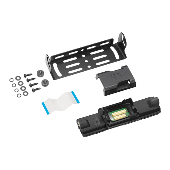
(2) Remove the flat cable from the display unit connector of the panel. 2.1.1 Installing the Remote Kit (KRK-18H, KRK-19B) The KRK-18H and KRK-19B remote kit is used to remotely operate the NX-3720/3820 series transceiver. The KRK-18H is connected to the NX-3720/3820 operation panel with the KCT-71 remote control cable. - Page 4 Molding Cover Molding Cover (1) Insert the flat cable attached to the interface unit (XC3- 063M-00) of the KRK-18H into the display unit connector of the panel. (Fig.4) (The cable has been pre-inserted in the connector of the KRK-18H.)
- Page 5 The KRK-18H and KRK-19B are optional units for the NX-3720/3820 designed to separate the Mobile transceiver and Control Head using the Remote control cable (KCT-71). The KRK-18H is a back panel for the Control Head and controls the Control Head and it consists of power supply circuit, audio circuit, control circuit, and external I/O circuit.
- Page 6 XC3-063 39DC IC30 MPU core 3.9V DC/DC 1.2V DC/DC MPU, Mobile DDR 39DC 1.8V DC/DC Level shift 18D_Flash Flash memory Switch MPU I/O, Flash memory CAN transceiver 3.3V AVR Audio circuits 3.3V AVR 53DC CAN transceiver 5.3V DC/DC Level shift for DM detect 5V AVR AUX Interface CN48...
- Page 7 The RX audio signal is controlled of the amplitude according to the volume setting and amplified by the AF power amplifier in the Mobile transceiver. The amplified signal is going through the KRK-19B and the KRK-18H, and is connected to the speaker at the Control Head.
- Page 8 COMPONENTS DESCRIPTION TERMINAL FUNCTION 2.3.1 Interface unit (XC3-063M-00) (KRK-18H) 2.4.1 Interface unit (XC3-063M-00) (KRK-18H) Ref. No. Part Name Use / Function Pin No. Name Function DC/DC step-down converter (53DC) DC/DC step-down converter (39DC) /PRST I Reset signal Voltage regulator (33A)
- Page 9 Pin No. Name Function Pin No. Name Function - No connection R_SET0 - No connection O Switched +B power - Ground O Switched +B power 2.4.2 Interface unit (XC3-064M-00) (KRK-19B) O Switched +B power Pin No. Name Function O Switched +B power - No connection - Ground O 5.3V output...
- Page 10 Pin No. Name Function I 5.3V input - No connection I Switched +B power I Switched +B power I Switched +B power I Switched +B power O Ignition sense - Ground - Ground - Ground - Ground - No connection I Speaker signal I Speaker signal I Speaker signal...
-
Page 11: Disassembly
Insert and remove the flat-head screwdriver as shown in the figure. Insert the screwdriver within this range. 3.1.2 Remove the top cover from the shield cover (KRK-18H only) (1) There are three shield covers on the interface unit, the top covers can be removed. -
Page 12: Adjustment
KRK-19B Main Parts Assembled Parts Part Name Part Number Part Name Part Number MAIN PANEL A6C-0089-00 STANDARD LABEL B4C-0632-00 SECTION 4 ADJUSTMENT This service manual does not describe ADJUSTMENT. (There is no adjustment item on KRK-18H and KRK-19B.) 1-12 (No.RA062<Rev.001>) -
Page 13: Troubleshooting
A flowchart for determining whether or not the transceiver can be powered on (the LCD does not function even if the power switch is turned on) due to broken BGA parts. Connect to the Control Head and RF Deck of the NX-3720/3820 using the KRK-18H, KCT-71 and KRK-19B. - Page 14 Checking the Flash Memory reset signal output from the MPU When Anode side of D13 is not Standard voltage, Points to be checked Standard voltage check R167. /FRST Fail If R167 is normal then the Flash Memory is broken. D13 (Anode side) 1.8V When Cathode side of D13 is not Standard voltage, the D13 (Cathode side)
- Page 15 When the transceiver starts to receive data, the [LOADING] display on the LCD. The Firmware is written to the RF Deck (NX-3720/3820) and the KRK-18H at the same time. f) If writing ends successfully, the checksum is calculated and a result is displayed.
- Page 16 Mobile transceiver, KRK-18H, KRK-19B, KCT-71, regulated DC power supply, programming interface cable (KPG-46U or KPG- 46X) and power cable. (3) While FLDM terminal has a short-circuit with GND terminal on the KRK-18H PCB, turn its power ON. Left: FLDM terminal Right: GND terminal 1-16 (No.RA062<Rev.001>)
- Page 17 (4) Upon startup of FLDM loader, "FIRMWARE PROG" appears on an LCD screen. (5) Start KFL up, select the desired firmware you wish to overwrite, select the COM port number and baud rate, and then click the "Write" button. Note: Configuring "Auto"...
- Page 18 MEMO...
- Page 19 PRECAUTIONS ON SCHEMATIC DIAGRAMS * Due to the improvement in performance, some part numbers shown in the circuit diagrams may not agree with those indicated in the Parts List. * The parts numbers, values and rated voltage etc. in the Schematic Diagrams are for reference only.
- Page 20 PRINTED CIRCUIT BOARD INTERFACE UNIT (XC3-063M-00 (KRK-18H_M) --- Component side view/Side A (J7C-0267-00) --- KRK-18H R123 TL41 TL39 TL38 IC30 R203 R108 R103 C113 C109 C192 R190 C112 TL22 TL21 C105 C208 C100 CN48 R104 IC13 C101 CN48 XC3-063 C110...
- Page 21 A-1C ADDRESS TABLE OF BOARD PARTS Y axis Side Each address may have an address error by one X axis interval. REF.NO. LOCATION REF.NO. LOCATION REF.NO. LOCATION REF.NO. LOCATION REF.NO. LOCATION B- 1B B- 3A C131 A- 4A A- 1A B- 4B B- 1B B- 3A...
- Page 22 INTERFACE UNIT (XC3-064M-00 (KRK-19B_M) --- Component side view/Side A (J7C-0268-00) --- R107 R106 ADDRESS TABLE OF BOARD PARTS C103 Each address may have an address error by one interval. C101 XC3-064 A-1C Y axis Side X axis J7C-0268-00 REF.NO. LOCATION REF.NO. LOCATION REF.NO. LOCATION R107 A- 2A C106...
- Page 23 SCHEMATIC DIAGRAM INTERFACE UNIT (XC3-063M-00 (KRK-18H_M)) $CN29 13.6V AUXo1 F10-3226-10 Shield case for 53DC AUXo0 53DC TPS54040DGQ 2.2k 2.2k $R87 2.2k 1.8V 2.2k $R89 5 4 3 2 1 2.2k 3.3V 2.2k $R88 2.2k F18-0026-00 $R90 Shield case for OMAP TL34 5.3V IC29...
- Page 24 INTERFACE UNIT (XC3-064M-00 (KRK-19B_M)) SPG_0 $L26 Separate I/F SPO_0 2.9V /PRST $R43 /PRST C101 /PSW $R44 /PSW 100p MICA+_0 MIC+ MICA-_0 MIC- 13.6V $R69 $C65 0.1u $C69 $R70 STBY C103 100p SPO_0 5.3V 3.3V SPG_0 VoUT 0.1u 470p CAN+ CAN+ BU33TD2WNVX CAN- CAN-...
- Page 25 INTERCONNETION DIAGRAM IC201 IC601 INTERFACE UNIT AF AMP RF POWER MODULE LA4631VC-XE KRK-19B KRK-18H CN48 ESD_GND R_SET0 R_SET0 R_SET1 R_SET1 INT SP R_SET2 R_SET2 CAN- 16 CAN- ESD_GND CAN+ 15 CAN+ A[23] A[23] 14 GND 13 GND D[0] D[0] 12 SPG...
- Page 26 BLOCK DIAGRAM KRK-18H KRK-19B AUX PORT KRK-18H Interface Unit (XC3-063) KRK-19B Interface Unit (XC3-064) 18D_Flash mDDR FLASH Memory IC23 CN48 IC29 /CS2,A[23:0], D[15:0] Poly Switch Level Shift AUXO0 ESD Protection AUXO1 Q1,Q3 D8,D9 EMIF /CS4,A[23],D[7:0] Level Shift AUXI0 ESD Protection...
- Page 27 PARTS LIST [KRK-18H, KRK-19B] * SAFETY PRECAUTION Parts identified by the symbol are critical for safety. Replace only with specified part numbers. * BEWARE OF BOGUS PARTS Parts that do not meet specifications may cause trouble in regard to safety and performance.
- Page 28 Exploded view of general assembly and parts list (KRK-18H) Block No.M1MM INTERFACE UNIT<01> General assembly Block No. [M][1][M][M] Symbol No. Part No. Part Name Description Local A2D-0026-00 REAR PANEL B4C-0632-00 STANDARD LABEL FCC/CANADA/ADDRESS F0G-0002-00 MOLDING COVER F10-3225-05 SHIELDING COVER...
- Page 29 Exploded view of general assembly and parts list (KRK-19B) Block No.M2MM INTERFACE UNIT<02> General assembly Block No. [M][2][M][M] Symbol No. Part No. Part Name Description Local A6C-0089-00 MAIN PANEL B4C-0632-00 STANDARD LABEL FCC/CANADA/ADDRESS F0G-0002-00 MOLDING COVER G0B-0118-00 EARTH SPRING N80-2608-48 P.HEAD T.SCREW (x4)
- Page 30 Electrical parts list INTERFACE UNIT Symbol No. Part No. Part Name Description Local XC3-063M-00(KRK-18H) CK73HB1H182K C CAPACITOR 1800pF 50V K *Note : This part cannot be replaced. There- CC73HCH1H101J C CAPACITOR 100pF 50V J fore, this part is not supplied as a service part.
- Page 31 Symbol No. Part No. Part Name Description Local Symbol No. Part No. Part Name Description Local C150 CK73HB1E104K C CAPACITOR 0.10uF 25V K RK73HH1J473D MG RESISTOR 47k 1/16W D C155 CK73FXR0J226M C CAPACITOR 22uF 6.3V M RK73HB1J100J MG RESISTOR 10...
- Page 32 INTERFACE UNIT Symbol No. Part No. Part Name Description Local XC3-064M-00(KRK-19B) R193 RK73HH1J103D MG RESISTOR 10k 1/16W D Block No. [0][2] R194 RK73HH1J103D MG RESISTOR 10k 1/16W D R197 RK73GB2A000J MG RESISTOR 0 1/10W J Symbol No. Part No. Part Name Description Local...
- Page 33 Packing materials and accessories parts list (KRK-18H) Block No.M3MM Packing and accessories Block No. [M][3][M][M] Symbol No. Part No. Part Name Description Local ------------ PAMPHLET Manual ------------ PAMPHLET WEEE/FCC E3G-0065-00 FFC WIRE 60pin ------------ ANTI-STATIC BAG REAR PANEL ------------ PROTECTION BAG(80/120/0.07)
- Page 34 Packing materials and accessories parts list (KRK-19B) Block No.M4MM Packing and accessories Block No. [M][4][M][M] Symbol No. Part No. Part Name Description Local ------------ PAMPHLET Manual ------------ PAMPHLET WEEE/FCC/Dealer/ADDRESS ------------ PROTECTION BAG MOLDING COVER ------------ PROTECTION BAG(125/250/0.07) MAIN PANEL H5A-1366-10 ITEM CARTON 3-8(No.RA062<Rev.001>)
- Page 35 MEMO...
- Page 36 JVC KENWOOD Corporation Communications Systems Division (No.RA062<Rev.001>) Printed in Japan...
Need help?
Do you have a question about the KRK-18H and is the answer not in the manual?
Questions and answers