Table of Contents
Advertisement
Quick Links
Please read the guide in full before starting your build. If it is blatantly obvious you haven't read it
and contact us for help then don't be surprised if we tell you to read the guide again... harsh I know.
Parts List
R1
1m
R12
R2
33k
R13
R3
100k
R14
R4
470k
R15
R5
15k
R16
R6
100r
R17
R7
1k
R18
R8
8k2
R19
R9
100k
R20
R10 10k
R21
R11 470k
R22
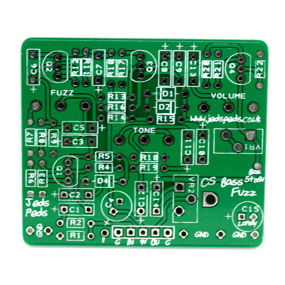
Kit Specific Build Notes
•
T1 is used to set the bias of the boost transistor. I have added a bias pad onto the pcb to
enable you to measure this. Between 5 and 6v is recommended. You will need a multi meter
to measure this voltage.
•
T2 is the boost level. This is totally up to you to decide. If you are inclined to do so, you could
swap this for a pot.
www.Jedspeds.co.uk
CS Bass Fuzz PCB Kit
100r
C1
220N
8k2
C2
1N
100k
C3
220N
470k
C4
47UF
15k
C5
220N
100r
C6
1N
33k
C7
220N
33K
C8
220N
33K
C9
1N
1M
C10 220N
1K
C11 4N7
C12
10N
C13
100N
C14
220N
C15
22UF
Q1,2,3
2N5088
Q4
MPF102
T1
5K
T2
100K
FUZZ
100KA
TONE
100KB
VOL
100KA
Advertisement
Table of Contents

Related Manuals for Jeds Peds CSound Bass Fuzz


Summary of Contents for Jeds Peds CSound Bass Fuzz
- Page 1 www.Jedspeds.co.uk CS Bass Fuzz PCB Kit Please read the guide in full before starting your build. If it is blatantly obvious you haven’t read it and contact us for help then don’t be surprised if we tell you to read the guide again… harsh I know. Parts List 100r 220N...
- Page 2 Schematic for Reference General Build Instruction The first thing you must do is identify your parts from the pack. As a rule, I build from small to big – therefore step one will be to identify the resistors and any diodes inside your kit. Each kit has a parts list at the top of the guide.
- Page 3 you may receive a “normal” pot on occasion and you will have to wire it. It’s not that inconvenient now is it. The other options for pots are that they are wired into place or the PCB hangs from them. Hooking up the Jacks Our kits come with mono jacks.
- Page 4 TEST THE BOARD When you get to the stage with the board and pots wired you need to test the board before you add the foot switch. Firstly, don’t put it in the box – I see people building inside a tiny enclosure and I wonder why.
- Page 5 The pins on the switch must run left to right like this, so the top row of pins would be 1, 4, and 7. If you put it in with 1, 2, and 3 across the top row you are wrong. To help you a little further with ensuring the orientation of your switch is correct.
- Page 6 The 2k2 resistor can be any value up to 4k7. You will have a spare in the kit to use. Good luck and happy soldering! PCB Design Notes 1. All PCBs are designed by ourselves, and tested before sale. 2. Box caps are shown with a + polarity mark on the silk screen, this is irrelevant as the box caps are non-polarised so can go either way.
Need help?
Do you have a question about the CSound Bass Fuzz and is the answer not in the manual?
Questions and answers