Advertisement
Quick Links
Advertisement

Related Manuals for SCALE-PARKFLYER BF 109 FATTY

Summary of Contents for SCALE-PARKFLYER BF 109 FATTY
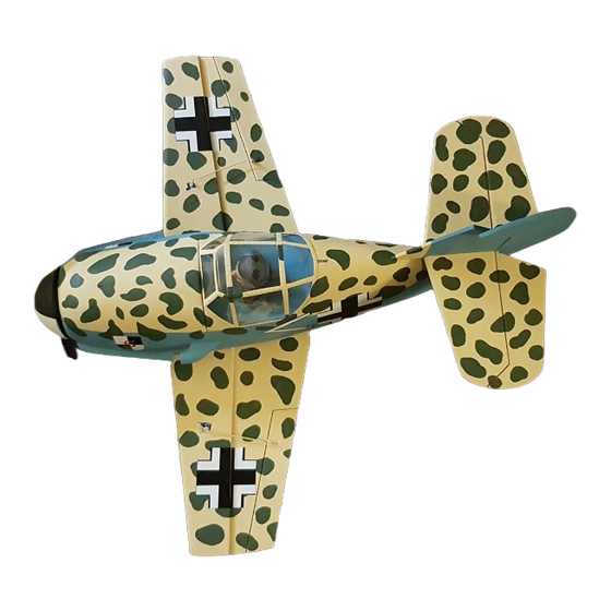
- Page 1 BF 109 „Fatty“ From the Fatty Season:...
-
Page 2: Building Instruction
Building Instruction The RC model of the BF 109 as a "cartoon variant" is part of the Fatty season, which is available here in the webshop. The models are simple in construction and allow quick construction progress. The wing consists of only a few components. The selected "KF" profile thus facilitates assembly. - Page 3 General: The DEPRON building material is a very light building material that is normally used in house construction. In hardware stores it can be found in wallpaper departments under the name "Unter...
-
Page 4: Part List
Partlist: Pos. Bezeichnung Anzahl Material Fuselage 6 mm Depron Fuselage lower part 6 mm Depron Longitudinal Fuselage framework 6 mm Depron Frame 1 6 mm Depron S2 - S6 Frame 2 until 6 je 1 X 6 mm Depron Canopy Frame 6 mm Depron Canopy Frame 3 mm Depron... - Page 5 Position of all Components:...
- Page 8 Building Instruction: Wing: Assembling the Heling Prepare wing parts T1 to T4. To do this, place the wing T1 and T2 on the heling and lightly grind the glue joint until they fit together without a gap.
- Page 9 Use a 6 X 0.5 mm or 8 X 0.5 mm carbon flat bar to reinforce the wing. To do this, cut into the marking along the wing so that the carbon rod can be inserted without play. The flat bar should be flush with the underside of the wing.
- Page 10 Adjust the upper parts of the wing (caron rod may need more space in the Depron) and sand the glue joint. Do not stick on yet!
- Page 11 Insert the ailerons using the hinges.
- Page 12 Prepare the aileron servos. Extend the servo cable until the connectors reach sufficiently into the fuselage area. Adjust the servos to neutral and glue them flush to the bottom of the lower wing. Cut a cable duct into the lower and upper wing. It is sufficient to notch a "V"...
- Page 13 Glue on the upper wing. Sand the leading edge: Like every profile, sand the leading edge up to 2/3 and down to 1/3. The KF step must remain sharp!
- Page 14 Fuselage: Insert frames S1 to S6 into the trunk stringer R1 starting from the rear and glue them flush with R1. S1 is in two parts.
- Page 15 Now the longitudinal stringers R2 can be pushed in sideways, aligned and glued. Now insert R3 and R4 according to the drawing and glue them together. The top edge of R4 should be flush with R1.
- Page 16 Now sand all components together so that the planking will later lie flat on the joints. Let the tail run out to a point.
- Page 17 Preparation of the first hull paneling. Marking must be inside. Carefully pull the planking over the edge of the table with the ball of your hand until the radius of the trunk is approx. Do not pull immediately with too much pressure so that the Depron does not break.
- Page 18 The planking should be pre-milled as far as:...
- Page 19 Place the fuselage in the sheeting. The marking of the adhesive surfaces is an orientation, the material overhang does not allow the planking to be perfectly aligned. Excess material is trimmed later. The bonding can be done with z-b. UHU POR take place. To do this, coat both components, place baking paper between them (UHU POR does not stick together), align the body and pull out the baking paper piece by piece.
- Page 22 Cut off the excess material up to the middle of R1 Carefully cut off the area of the wing. To do this, lay the wing on several times until the cladding on the wing is separated without gaps.
- Page 23 The cladding can be cut off by connecting the front edge S1. The planking now ends with R1 bow.
- Page 24 Place the hull reinforcement R6 flush with the planking. In the rear area, R6 must be sanded a little until it rests against the planking. If the shape of the planking did not run optimally, the course can be adjusted during the gluing process until it has hardened.
- Page 25 Now that the servos and Bowden cables for rudder / elevator are used, prepare the rudder & elevator unit. The tailplane can be completely prepared. Insert a 6 mm piece of pine wood as a rudder connection, insert the hinges.
- Page 26 Just prepare the rudder, don't glue the rudder yet!
- Page 27 To stiffen a carbon flat bar 6X05 mm insert into the fuselage and glue it perpendicularly. Prepare the gap in the vertical stabilizer. Put everything together for control (including the tailplane). Check whether both rudders have enough space for max. Rudder deflection.
- Page 29 Insert servos, prepare Bowden cables. Course of the Bowden cables through the fuselage. The position at which the Bowden cables should run out of the fuselage can then be checked with the tail unit attached.
- Page 32 Prepare the second fuselage sheeting for gluing to the fuselage.
- Page 34 Place the rudder floor pull through the planking before gluing:...
- Page 35 Let the glue joints overlap at the top and bottom and as soon as the cladding sticks over a large area, adapt the cladding to the finished side.
- Page 39 Prepare to attach the wing. There are multiple possibilities. - Fixed gluing of the wing to the fuselage. - Wing attachment by means of elastic bands - Wing attachment by means of bolts and plastic screws. Wing attachment using elastic straps:...
- Page 41 Wing attachment using bolts and plastic screws:...
- Page 42 For each variant, attach and align the wing. Lay frames S2a to S4a with R1a in the middle of the wing.
- Page 43 Pre-bend the planking. Sand / cut the adhesive surface at an angle, adjust and glue it.
- Page 45 to glue the vertical stabilizer, align it to the fuselage / wing. Insert the horizontal stabilizer, also align this geometrically. Glue the rudder tightly.
- Page 46 Struts can be used in the same way as the original to stiffen the tail unit. Coffee stirring sticks can be used for this.
- Page 47 Now insert and adjust the drive motor. A stiffening in the Depron hull is absolutely necessary in order to initiate the force. Sufficient stability can be added using plywood and carbon rods. Here, as an example, a 3D printed motor holder was used, the force transmission of which goes to frame S1 with plywood.
- Page 49 Prepare the spinner. To complete the spinner, a support plate made of 1.5 mm plywood, better 0.5 mm GRP, is required. Diameter 104 mm. Adapt the Depronring T8 to the shape of the spinner by grinding this conical until the spinner fits well into the ring. Glue the ring T8 onto the carrier plate.
- Page 51 Prepare cutouts for the propeller.
- Page 54 Finally, the PVC2 spinner can be glued to the carrier plate with UHU POR. Important: glue together wet to have enough time to align the spinner so that it runs smoothly without imbalance.
- Page 56 Connection of all servos. For the optics, the cooling water cooler can be placed under the wing.
- Page 59 The canopy consists of the Depron parts K1 to K4. To prevent the canopy from sticking to the fuselage, protect the adhesive points with scotch tape. Put on K1 to K3 and glue them together.
- Page 60 For the subsequent locking of the canopy as access to the fuselage, for example Spigots are used and a car lock.
- Page 61 Put on the cabin (K4). The PVC hood sits "in front of" K1. Adapt and glue the unit.
- Page 62 Depending on the choice of drive motor and flight battery, the flight battery is in different positions. Weighing the model with all components to determine the center of gravity. The center of gravity is on the wing leading edge at: 67 mm In this case (construction 1) directly below the canopy.
- Page 64 Details and paintwork. Now the model can be completely sanded. For glue gaps, “Modelier” “Moltofill”, a kind of paste for touching up plaster, can be optimally used to fill the gap. After curing, the material is hardly harder than Depron and you have a clean shell in your hands.
- Page 66 Painting: I recommend “Kreul” water-based paints for the finish. Depron, lightly sanded, can be rolled out contour-free with a soft paint roller. If you want to achieve a little more stability, you should apply "Aqua Clou" (water-based) parquet varnish and coat it several times with intermediate sanding.
- Page 67 Prepared canopy for painting: RC system: Rudder deflections: height 20 mm, side 15 mm and transverse 15 mm on each side. Center of gravity: The center of gravity is 67 mm from the leading edge of the wing. Battery fastening: e.g. using Velcro in the bow (or as described in the instructions) of the fuselage Recommendation 3 S 1800 mAh.
- Page 68 Of course I will help with construction problems by phone or email. I am happy to call you back with an email request. Always have a good flight with your new model. Frank Seuffert info@scale-parkflyer.de...
- Page 69 Warning!! Before you fl y the R/C model it is essential to read the operating and building instructions in full. This sheet is part of the operating instructions. Please keep it in a safe place for further reference. If you ever sell the model make sure to pass on this sheet to the new owner together with the model. A remote controlled model aircraft (model plane ) is not a toy.
Need help?
Do you have a question about the BF 109 FATTY and is the answer not in the manual?
Questions and answers